Free Fridge -or- The Collaborative Cooler

“Think free as in free speech, not free beer.”   -Richard Stallman

Refrigerators are not software, but they could be designed and shared freely like software.  Granted, I’m talking about hardware: steel, glass, copper, insulation, etc., but why not have an “open design” refrigerator?  Why not build things like we gave a damn about the future?  Why not consider the unborn generations, and the impact our decisions today are going to have on them?  Can’t we do better?  Isn’t that what progress should look like?

  • Constant improvements
  • Cradle to cradle design
  • 100% recyclable  (Not just down-cycled)
  • Modular
  • Serviceable
  • Technology that ensures our species survival, rather than ensures its demise


Why a Refrigerator?

I focus my attention on the domestic refrigerator (and you’ll be seeing a lot more about this, so sit tight) because, although it may not be the most crucial technology for our survival, I think most people would put it high on their list of necessities if really forced to think about it.  There are hundreds of machines that should be re-invented, but my personal obsession is the refrigerator – I think they’re neat, while most folks remain largely indifferent.  So, it’s my thing, and I’d like to afford others the opportunity to take notice of the heat pump in their kitchen.  Shall we begin? Read more ›

Advertisement
Tagged with: , , , , , ,
Posted in Philosophy, Refrigeration, Refrigerator

Disposable Refrigerator and Something Better

The modern domestic refrigerator doesn’t use much more electricity than refrigerators from the 1940s.  Admittedly, modern models have greater volume, and no need to manually defrost, but it remains to be seen just how long they will remain functional.  What is omitted from that silly EnergyStar tag in your new fridge, is the energy cost, and environmental damage associated with its manufacture.  Copious amounts of petroleum based plastics go into the liner, shelves, door, gaskets, ice maker, hardware, and the insulation.  Oh, the insulation!  I don’t know if I should call urethane insulation “plastic” per se,  but in terms of its obnoxious environmental assault, urethane belongs in some sort of category with the rest of the trash in refrigerators.

“Trash” is the operative word here.  They make the machine.  We buy it.  It runs reliably for 10 to 15 years.  If it breaks at any time, or is otherwise viewed as a shadow of its former self, the machine is discarded; not necessarily recycled, but mostly just thrown away.  Yes, in some cases these refrigerators are separated into their component parts as much as practicable, but the vast majority of the millions of refrigerators thrown away each year in the US are not.

And what about the distance it travels?  So much of what we use in the United States comes from southeast Asia.  I don’t mean to sound like a chest thumping, flag waiver – I’m certainly not, but I feel that the amount of resources which go into every refrigerator to just get it to our homes, is immense and unnecessary.  We can make things here, and we can make them under a radically different model than globalized capitalism.

What I propose is an open design refrigerator, built locally, if not by the users themselves.  Read more ›

Tagged with: , ,
Posted in Refrigerator

Disposable Refrigerators

I hardly know where to start, but that is why I am writing about this – to get my thoughts somewhat in line.

What happened to technology?  I know that is a broad question, probably too broad so I’ll narrow it down a bit.  Why is so much of what we buy, junk that is destined for the scrapheap or landfill, the day it is brought home?

I could attempt a long and boring explanation (as I see it) of competition, the profit motive, market saturation, planned obsolescence, intrinsic obsolescence (very scary), and the unaccounted environmental costs associated with the manufacture, distribution, marketing, sale, consumption, and disposal of typical consumer goods.  I am not going to do that since the above sentence was long enough as it is, and I prefer opinions over facts – no one expects citations for opinions.

What I am going to do is propose some simple, and technologically not-so-simple, suggestions for a sensible set of guidelines for one of the most overlooked and under-appreciated features of modern living: the refrigerator.

I strolled through Home Depot recently to see what kind of refrigerators are currently available. I  was kind of impressed by what I saw.  There are so many features available, beyond just the freezer top or bottom, and the side by side.  I found several very good ideas for organizing refrigerated goods, but nothing really new.  With the exception of the use of copious quantities of plastic that makes the cabinet smell like a petrochemical factory, I did not see one genuinely original cabinet design or feature which hasn’t been around since at least the 1940s.  Granted, some of these convenient door designs, extra drawers, and multiple evaporators, were good ideas then, and I’m glad these manufacturers are bringing them back.

Unfortunately, I feel these space age refrigerators are built on the same old junk of yester-year, with the exception that now, production happens in China, which by itself doesn’t suggest they are junk, but along with a number of other cost saving factors means that the components do not need to last much longer than the consumer expects to have it (10 to 15 years?)  Actually, some of the domestic systems of the WWII era are still humming along in basements and garages, while the $4000 units for sale today won’t likely be any good by 2030.  Even if an owner wants to repair one of these overpriced monsters, good luck acquiring parts for it, or getting it fixed after the warranty has expired.

And what’s with all the frigg’n touch-pads, and LCD screens?  Do we really need Pandora internet radio on the god damn refrigerator?  Forget about the stupid EnergyStar rating, when server space to handle your Twitter account probably consumes more electricity than the compressor of that monster Samsung.

Some of the strangest things about our culture surround the fact that we manufacture and use “single use disposable” items, but we make them out of a substance that will be with us for thousands of years, producing untold health and environmental damage.  Well, it appears that the development of our household appliances are well on their way to mimicking the “use it and throw it away” cycle.  Yeah, some plastics can be recycled once or twice, but plastic recycling is more of a distraction than a solution.

We can do better, and I see no point in waiting for industry to do something about it.  That will be in the coming posts.

-M.C. Pletcher


Tagged with: ,
Posted in Refrigerator

Change of Course – 3 ? 4 ?

This is at least the third or forth time I have decided to change the course of this blog, and my focused area of research.  You could say I wander wherever my attention is captured.  I remain interested in all subjects written of prior to this date, however my immediate course of action will put those interests on the back burner for now.  We remain in a motorhome in the pacific northwest, renting a comically small plot of land for an obscene amount of money.  In time we will find cheaper accommodations, but for now, this suits us until we both settle into our new jobs.  We are quite close to being out of debt; 20 months on a 60 month loan – not bad, eh?

For a while there, I was very focused on building a tiny home of some sort.  I still have aspirations to do so, but currently have no prospects as to where I would build it, or where I would park it.  Due to this double dilemma, I feel the time is not yet right for that, and I should just sleep on the idea – for a few years.

The work I have been doing with ejector and flooded evaporator is much too valuable (and so much fun), that I can’t let the dust collect on that equipment.  These technologies were going to be implemented into a heat pump for this winter, but for a number of reasons, I chose not to rush into such an extensive project until I feel more confident in my abilities.

It was some recent work I did, as a collaborative project with a fella I met through my YouTube channel, that has me interested in focusing on small appliances.  I attempted a very small dehumidifier with a Coke can sized brushless DC compressor.  I learned rather quickly that either I don’t know what the hell I’m doing, or the the parts I utilized were mismatched (probably both).

It was in conversation with my friend who got the compressor for me, that we decided the compressor (or similar) would be suitable for a small refrigerator/freezer.  Now my interest in refrigerators is no secret.  There are a large number of posts on this blog pertaining to antique refrigerators, and perhaps as many about my own thoughts on refrigerators.  It would seem that I may have a new project, which at this moment in time, just feels right:  I want to build a better refrigerator.

-M.C. Pletcher


Posted in Dwelling, Personal, Refrigeration, Refrigerator, The Squatch, Tiny House

Heat Pump or Heat Engine?

I haven’t bent any copper for a few weeks now.  Between the heat, a vacation, and some bad habits, the shop has barely been opened.  Part of the reason is due to a recent fascination with power plants.  Previously, in The Power Plant -or- The Wood Fired Refrigerator, I discussed the possibility of abandoning vapor compression heat pumps for a biomass source.  My opinion hasn’t changed greatly in that time, but what is up in the air right now, is whether or not to abandon my current vapor compression work, and focus on heat engines instead.

As my work with ejectors stand, I feel that I’m making progress, and in time I’ll have a self regulating flooded evaporator.  The plan was to acquire a large outdoor heat pump coil and modify it for flooded operation.  A small hermetic compressor, supplemented by an ejector primary, would pick up heat from the outdoor environment this winter, and condense the propane refrigerant in a water holding tank.  This water would then be circulated via pump into a water to air heat exchanger in the motorhome.

As of this date, that basic design has not changed.  What has changed, is my opinion of domestic heating with grid powered vapor compression.  Read more ›

Tagged with: , , , , , , , , , , ,
Posted in Personal, Refrigeration, The Squatch, Water

The Power Plant -or- The Wood Fired Refrigerator

I don’t like heat pumps.  Wait, let me rephrase that:  I don’t like grid tied heat pumps.  It’s the electricity!  Heat pumps are an amazing technology which I am currently obsessed with, and I am in fact in the process of building one to heat my motorhome this winter.  It will be grid tied.  I am not doing this to save money, for the propane I heat with now is much easier, and cheaper.  The heat pump won’t pay for itself in dollars and cents, but it will teach me a great deal about the thermodynamics and construction methods, and that – is priceless.

The Grid

Electricity is an amazing medium to convey energy, but the way we utilize it now, that is all it is:  a medium.  Electricity is not a source of power, it is a means to convey power from coal fired steam plants, hydroelectric dams, wind turbines, nuclear fission, and a few other sources.  Due to the economy of scale, these sources are able to operate at reasonably high levels of efficiency, and convert potentials (chemical energy, water pressure, air pressure, etc.) into relatively high voltage potentials, which are transmitted across vast distances to power our homes.

Electricity is an amazing medium to power lighting, electronics, charge batteries, and intermittent home appliances.  When it comes to heating a home, I’m not so sure that grid electricity is the way to go.  Resistive heating elements are an atrocious destruction of exergy, and will not be discussed further.  Electrically operated fans and pumps for a biomass or fossil fuel system are reasonable, and may be low enough in wattage to be powered by off grid, home power generation systems.  A heat pump, on the other hand, is not likely to be powered by an off grid system.  Their consumption is just far too large, and although a fraction of a resistive system (I said it again), not small enough to be powered by PV or wind.

Other Options

But wait!  Read more ›

Tagged with: , , , , , , , , , ,
Posted in Dehumidifiers, Dwelling, Hot Water, Philosophy, Refrigeration, Refrigerator, Tiny House, Water

Ejector Assembly Construction

This is a three part series on refrigeration ejectors.  Part I on theory, is Ejectors in Refrigeration – an Expressor, and Part II on manufacturing techniques, Handmade Copper Ejector.

There is a lot of video media, so I will jump right in.  I ramble a lot. 😉

20150721_191526First, I thought I would share these weird things.  I call them “Ravioli fittings”.  As will become apparent shortly, I have an evaporator coil I harvested from an air conditioner, and the way it was plumbed wasn’t exactly what I had in mind.  I desired to feed liquid refrigerant to the bottom, and have it exit from the top, rather than go up the front set of coils and down the back (it’s a two layer heat exchanger).  Read more ›

Tagged with: , , , , , , , , , , , , , ,
Posted in Refrigeration

Handmade Copper Ejectors

This is part two of a three part series to get my blog up to date on my ejector research.  Part I was about ejector theory:  Ejectors in Refrigeration – an Expressor.  Part III is about assembling and testing:  Ejector Assembly Construction.

Within two weeks of studying refrigerant ejectors, I decided I might as well try my hand at building one.  Well, let me say, I thought refrigeration itself was an obscure hobby, that is until I tried to find ANYONE who has worked with ejectors, outside of universities and industry.  What I had to go off of, is some passages in antiquarian books on steam ejectors, a handful of digital papers in the research category, and a number of patents.  Have I mentioned how much I LOVE Google Patent Search?!

As my machining skills are essentially non-existent, and my material of choice is copper, that seemed likely as my ejector material.  Some ejectors are made by metal spinning and welding, some are machined, and some are cast.  Copper spinning is something I would love to get into, and I believe a fantastically useful skill to have, however it would require a lathe (which I do not have), as well as a machined form (refer to previous parentheses).

I’ve tried widening a piece of copper tubing, such as by driving a tapered mandrel into some annealed 3/8″ tubing.  It is quite difficult to do.  I’ve tried spinning the tubing onto the mandrel with great force.  The mandrel was too big for the drill chuck, so I had to mash the copper in it. 😉  Doesn’t matter – didn’t work well.  I thought I had found a route to success when I stretched a piece of 1/2″ hard drawn copper pipe with a hydraulic “Port-O-Power”.  As it pulled, I would heat the center with a torch.  It worked for a while, but then the copper got too thin and broke.  Raspberries. Read more ›

Tagged with: , , , , , , , , ,
Posted in Refrigeration

Ejectors in Refrigeration – an Expressor

Having developed a degree of confidence with copper brazing, and reaching the potential limits of what can be learned, I have decided to move past my original work with the Ebullator.  I document my progress with that device in Refrigeration Test Bench I, RTB II, and RTB III.

Ejector refrigeration devices were not something I had planned on messing with for some time, if ever.  I spend a great deal of time at my work (truck driver in Portland) thinking about how I would like to proceed with my hobby.  At times I run through hundreds of iterations of a particular device which I’m currently working on, and other times I will theorize on fanciful devices which may improve performance in a vapor compression system, but may never be explored further.  A great tool in my mental kit, is the log(pressure) – enthalpy diagram.  Other tools include factors like entropy, or more usefully:  exergy.

While attempting to design a device which would preserve some of the lost exergy in the expansion of high pressure liquid refrigerant passing through a metering device into the low pressure portion of a refrigeration system, I considered the expanders used in some air refrigeration systems I’ve read about, which recover the potential energy of a a compressed gas, and return it to the compressor, generally as shaft work.  The potential difficulties of such a device, especially concerning a very small application, are many, perhaps the worst being the small change in specific volume a refrigerant undergoes when it is lowered in pressure while remaining in the liquid state.  A reciprocating expander is out of the question, and a turbine is quite simply beyond my technical abilities.

It was in quite a roundabout way, that I began to understand the way in which an ejector functions, Read more ›

Tagged with: , , , , , , , , , , ,
Posted in Refrigeration

Sealing Thermocouples Into Refrigeration Lines

I thought I would provide some media to help describe my method of installing thermocouples into refrigeration lines.  I’ve found in working with the Ebullator, that the temperature readings I was getting by taping thermocouple tips to the outside of the copper lines of interest, were not particularly trustworthy, and did not have the response time I was seeking.  It was suggested to me by a friend, to install them directly in the system, so that readings were taken from the passing liquid or vapor streams.  I don’t believe he was exactly sure how to accomplish this, nor was I; the pressures these devices would be exposed to could be in excess of 350 psi.

I chose to embed the thermocouple lines in a casting of epoxy, such that the tip of the thermocouple would be suspended in a brass tee with male 1/4″ flare fittings.  A short copper stub would be made to fit to the central fitting, whereby the thermocouple wire would be run down through said stub.  Epoxy would be poured into a form made from a piece of flexible tubing or pipe, and poured epoxy would seal off the relatively higher pressure refrigerant gases from escaping.  My first concern, was that the gases would leak through the fiberglass wire shielding, regardless of the epoxy casting.  I was right.

I found that I would have to shave away a portion of the shielding, leaving bare wires, in order to provide a “break”, where the epoxy could envelop the wires and effectively seal against refrigerant gases.  Further problems were encountered when I rushed the testing of these devices, only allowing the epoxy to cure for approximately one hour.  The nitrogen pressure test resulted in device failure, and further restorative castings were of no use without allowing for proper cure time.

Finally, after two failures, I was able to produce these embedded thermocouple devices in single castings, by allotting a full 24 hour curing time.  I have since produced a number of these, mainly in the 1/4″ flared tee size, but also in a 3/8″ copper brazed tee, and an embedded 1/4″ size, brazed to a 1″ copper separator tank.  I feel confident in my production technique.

20150618_182939Here, you can see the metallic portion of the assembly, ready for a thermocouple wire.  The original purpose of the crimping in the copper stub, was to provide an effective mechanical “grip” for the epoxy, in order to avoid a catastrophic separation of epoxy and copper.  I still believe that logic is sound, and continue the practice, but I’ve found there is a second reason, and quite important at that:  You must avoid the flow of workable epoxy into the desired path of refrigerant flow.  I found this out the hard way, ruining at least two sensors.  The crimping helps to avoid this unfortunate end to some delicate work.  Other methods may be suitable to prevent this, but I am cautious against introducing other substances into the copper, as they may have deleterious consequences, possibly by being dissolved or reacted with the hydrocarbon refrigerant I work with.  (propane)  The many wraps of electrical tape are applied so as to fit the inside diameter of a piece of 1/2″ vinyl tubing, used as a casting form.

thermistor insulation stripped

thermistor tip in pressured line

20150622_185153

20150620_082409The green plastic, insulated thermocouple wire, is just another type I use.  I was hoping that this insulation would not pass gases through it, but I found, to my chagrin, that propane was escaping through the entire 30 cm length and exiting at the plug on my meter!  As you can see, I had to shave approximately one cm of insulation, in order to resolve the issues.  The bubbles in the casting do not seem to cause any problems.  It is important though, to agitate the epoxy while it is workable to avoid any large voids, especially below the height of the copper.  I accomplish this by sliding a used plastic wire tie down between the casting form and the copper.  I do this action only a few times, so as to avoid “pumping” it down the copper stub.

pressure testing thermistorThis was the setup for pressure testing.  This image appears to be of the very first experiment.  Later models have been tested to as high as 450 psi, without leaks.


This type of temperature measurement is probably not necessary for most projects, however I felt I desired direct readings for my current research.  With some thorough searching, I was unable to find anyone doing something similar for higher pressure applications.  I had to figure this out for myself.  At this date, I use a cheap two part epoxy purchased at Harbor Freight Tools.  It seems to do the trick, and results in a nice clear casting.  I hope this article has been of some use to you.

-M.C. Pletcher


Tagged with: , , , , , , , , ,
Posted in Refrigeration

Cannibalizing the Ebullator

I’ve moved on, in regards to what I think can be learned from the first flooded evaporator system, I have been calling “The Ebullator”.  Far too many limiting features were preventing me from moving on to the next step in my research, and the modifications needed would not have been worth the effort.  I chose to dismantle, and harvest the copper for the next project:  a finned evaporator coil.

20150711_131935

This is the last picture of the machine, before it was dismantled.  Several changes were made since the last post, including an air cooled condenser, a plastic sight glass, several embedded thermocouples, and a pneumatically controlled expansion valve.

20150706_053212

The extended view sight glass was made with a piece of 1/2″ OD polyethylene tubing, sealed with compression fittings.  Initially, it was a great success, allowing me to understand how the liquid level changed in the separator column under various system conditions.  I found that over the course of 12 hours or so, the continuous pressure exerted by propane under ambient saturated conditions, caused the tubing to swell into the shape you see above.  I removed the charge in the system as a precaution, and sought out a higher working pressure tubing.  I ended up with some nylon tubing with a 250 psi working pressure, as opposed to 100 psi for the PE.  The nylon is a little harder to see through, but has yet to swell like this.

I acquired an R-22 expansion valve, rated at 1/4 ton, and proceeded to cut the sensing bulb in such a way as to control the pressure on the power head with an air pressure regulator fitted to a small air tank I assembled.  I found this to provide easier control of throttling for the device.  Although I did not try utilizing the sensing bulb as it was intended, it was unlikely to function correctly, as the evaporator is designed for a flooded condition, and the suction gas is in a saturated state.

20150711_140810

Here you can see an “exploded view” of the system, after I dismantled it.  The evaporator unit itself was aesthetically pleasing, and would have been nice to keep, but I really could use the parts.  Out of the four coils, I have since straightened one of them, and used the copper for further developments.  I find the re-usability of copper to be fascinating and something I take pride in achieving.

The following post will provide some detail on how I have been manufacturing embedded thermocouples, to take refrigerant temperatures directly inside the lines.

-M.C. Pletcher

Tagged with: , , , , , , , , , , , ,
Posted in Refrigeration

Amateurish Refrigeration Research

I have a High School Diploma, and that is about the extent of my formal education.  My real education comes from years of mechanic jobs, fiddling with and fixing things around the house, building things I need rather than buying them, and of course books – lots of antique books.

Knowledge or interest in refrigeration does not require a college degree nor a position at General Electric.  I am a tinkerer.  I am not required to play by anyone’s rules regarding what is conventional or profitable.  My incessant ramblings do not have to be based in fact, nor does my analytical approach need to adhere to any “international standard”.  At times I may blather on about something I don’t really understand, and other times I may gloss over my methods simply because I am “fudging it”.

I do not care.  I am enjoying myself.

I have no specific goal, I am wandering for the simple entertainment of what lies beyond the next iteration of my machine.  Not an engineer by trade, I am an amateur, practicing for the sheer enjoyment of it all.

When this refrigeration research started back up a few months ago, I had decided the goal was to see how much ice a human powered machine could make in one hour.  I won’t outline every reason for this, but the main one was just because I thought it would be funny.  That’s really the crux of it.  It would also be difficult, and teach the need to squeeze out every possible increase in efficiency, due to the vicious feedback brought on by an hour of hard peddling for a small quantity of water ice.  The work I shared in Refrigeration Test Bench Part I shows the process of acquiring a belt driven compressor and building a simple refrigeration circuit driven by a treadmill motor.  The intention was to develop the system under electric motor driven conditions until I felt I could take over the work myself, and continue from there.  Unfortunately, I found limits to what I could accomplish with The York compressor running at a very low RPM.  I decided to switch over to a hermetic compressor for now, and focus on developing a better evaporator unit, as well as collecting data on the system so I can model the whole thing analytically.

Part III is where the system stands now, more or less.  Currently, inline thermocouples are being developed, where the sensors are sealed directly in the refrigerant stream, in order to provide more accurate, and more responsive readings. – temperature and pressure logging will be following in time.

There are so many ideas I want to explore, however I must develop a strategy for how I wish to proceed.  For my benefit, I’m going to outline that here:

  1. Finish developing thermocouple temperature sensors, and observe their performance in the current system.
  2. Design and build an evaporative cooler for the the condenser cooling water, in order to increase run times and maintain system pressures.
  3. Utilizing fluid temperatures, pressures, and refrigerant tables, crunch out some COP values based on specific enthalpies in the refrigeration circuit.  This will have little to do with compressor current draw, but will instead be based on “effective compression”.  Perform these calculations under various system conditions.
  4. Implement some manner of temperature logging.  Pressure logging would be a plus!
  5. Acquires and/or construct an easier to control expansion valve.  This may be a modified TXV or a computer controlled EXV.
  6. Design and build the second generation ebullator which will be made to create flat plate ice in a metallic can.  Special considerations will be made for appropriate sight glasses, and the possibility of an ejector type throttling valve.
  7. Install the ebullator inside of a small refrigerator cabinet for better control over air movement and insulation.
  8. Formulate some manner of “standard conditions”, and observe changes in COP, gaining a better understanding as to the performance.  A simple version of this COP will be the relative energy usage of the compressor for a given quantity of ice production. – essentially, “tonnage”.
  9. Design and build an ejector type “expressor”, which will conserve some of the kinetic energy of the high pressure liquid refrigerant exiting the expansion device, imparting it to the suction gas through a venturi device, thereby raising the suction pressure, lower the compression ratio, increase the refrigerating effect, and improve overall COP.  As of this date, I intend to utilize a manually controlled expansion device in the ejector, and perhaps a gravity float device to admit medium pressure liquid from a separator after the ejector, and pass it through to the plate ice ebullator.  This ejector expressor is a rather recent revelation of mine, which I thought for a short time was my own idea, but quickly found out it already exists, which is where I discovered some of the terminology.  Nonetheless, it is reassuring to find that the principle is sound, so I would like to investigate and test it myself.
  10. Compare the expressor device to a conventional expansion valve through the aforementioned methods.
  11. Investigate methods of subcooling high pressure liquid refrigerant through means of sky radiative cooling.
  12. Break out the York 210 compressor and re-adapt it to the system as it exists at that date.
  13. Determine the performance of the York 210 in terms of volumetric efficiency and investigate any means by which to improve upon it.  This will likely include a determination of the degree by which the refrigerant is miscible in the compressor oil, and the changes to the viscosity of the oil therein.
  14. If it appears possible to make the machine pedal powered, adapt a bicycle drive-train to the apparatus, at which point I will be the prime mover myself.  Study COP and the ice productive capabilities of human power.  Improve and repeat.
  15. Investigate the possibility of instituting other forms of compressors including turbines, liquid based U-shaped compressors, rotary liquid compressors, and of course variable speed hermetics.
  16. Build and investigate the performance of a grey water heater recovery – domestic water heater, a dehumidifier, a domestic heat pump, and a better refrigerator.
  17. Explore other methods of exergy conservation including petroleum powered compressors, wood gas, and solar thermal organic rankine.
  18. Have a beer or two.  Or three…

This is just a rough outline of some of my interests within the field of vapor compression technology.  These will change greatly in the coming months and years, but I’m sure the reader can appreciate the scope of what I believe I can accomplish if I keep up the level of obsession, I possess.

-M.C. Pletcher


Tagged with: , , , , , , , ,
Posted in Hot Water, Refrigeration, Refrigerator

Refrigeration Test Bench – Part III

In Part I, I shared a lot of media relating to my efforts in building a refrigeration test bench.  I intended to build the whole thing from a DIY approach, and utilize a York 210 – Belt Driven Air Conditioning Compressor.  I did some testing with a water cooled condenser and a dry type evaporator in a pale full of water.

In Part II, I try to explain the theory of design, and method of building my gravity flooded evaporator, or “Ebullator”.  In this post, I will share some of the more recent media, and initial observations, regarding the Ebullator performance, compressor issues, and the next steps I’m taking to model the system.


ebullator first runThis is a photograph taken just prior to the first run of the ebullator.  The rest of the system is the same as before.  The propane was charged as a vapor, into the suction line until a steady liquid level was observed in the ebullator sight glass, and a smooth sound was heard from the throttle.  The suction line insulation is not yet installed, nor are the four thermocouples.  The ebullator rests on a square of reflective foil insulation and 1.5″ of extruded polystyrene scrap I had.  I’m building a crude insulated box around it.


ebullator radiant boxThis is when the first tests began.  As you can see, I surrounded the ebullator with a simple box of reflective foil insulation.  The platform underneath is larger to support the polystyrene insulation which will be added later.  I was quite anxious to test it, so I went ahead and charged the system.


ebullator insulated boxWith what few pieces of polystyrene I had from a dumpster dive, and some ductwork reflective tape, I finished the box, with the exception of the top.  At one point, the air temperature in the bottom was at -36 degrees Fahrenheit.

Things change a bit from here on.  From the start, I wanted to construct my device with an open drive compressor, so that I could choose the power source as well as the operating speed.  I became aware of the York 210 automotive air conditioning compressor from a friend, and after considerable research I decided to retrieve my own from the local junkyard.  I was having so much fun with the thing that I went out and scrounged for three more; each one having slightly different features, configurations, and quality.  I intend to use some for various modifications I have in mind.

What I have found in working with the York that lubrication appears to be the primary problem.  Once I wised up, geared down, and made a smoother running test bench for the York, I find that the slow RPM of perhaps, 60 to 120 RPM, is not providing sufficient lubrication to the internal mechanism.  In other words, the damned thing squeaks and bangs a lot.  Because the York relies on splash lubrication from the crank case, I believe that the low RPM is not picking up enough oil from the bottom of the crank case, and components are rubbing dry, especially the piston seals against the cylinder walls.  This last point a a particular concern, since lack of an oil seal will allow gas bypass around the cylinder, and lead to a serious decrease in volumetric efficiency.

I have run both pharmaceutical grade mineral oil from Wal-Mart, and a mineral oil blend purchased from a local refrigeration supply house, the latter of which was designed for hydrocarbon refrigerants.  I have heard no difference in compressor noise.

Additionally, I have put two different compressors to work, and their apparent performance appears to be roughly the same.  I have been filling the crankcase with the manufacturer recommended volume of oil, and this may need to change if I hope to utilize these high displacement compressors for such a small load.  Although I have yet to add more oil as of this date, I think I will give it a try at some point.

A concern with adding more oil, is the high miscibility of propane in most lubricating oils.  This fact leads to a severe reduction in the viscosity of the oil, the lubricating effects, and finally loss of thin film oil seal around the piston.  I may need a higher viscosity oil, as well as some sort of oil separator to prevent compressor oil from migrating about the system, decreasing heat transfer and and being lost in the bottom of the ebullator.

And so, it was decided to change course for now, and focus on collecting data to model system performance, so that I can determine what the volumetric efficiency of the compressor is, and how it changes with various alterations.  In line with this thinking, it was decided to employ a fully hermetic compressor from a small appliance for longer, quieter running times, until such modeling can be made with some degree of reasonable findings.


hermetic compressor first run

The compressor I chose was salvaged from a 5,000 BTU/hr air conditioner.  It is a rotary unit, approximately 1/3 HP, and has proven to be quite a fun little pig to play around with.  I had to modify the inlet and outlet connections to adapt to my existing lines so that I can easily swap the York back in when I decide to, with little fuss and short down time.  I added service ports, but no service valves at this point.

The system goal from the start, was to build a pedal powered ice machine.  In order to accomplish this (if I ever do), I need an evaporator coild which will absorb heat from a quantity of water and lower the temperature to solidification.  I’ve considered utilizing a lowering freezing point brine to cool cans of water which will form ice.  I’ve since decided, that although that make be an effective method when producing ice continuously and on a large scale, a small batch produced in an hour would be more productive if unnecessary cooling, like that of the brine itself, were not being performed.  For that reason, I will likely be pursuing a flat plate heat exchanger with aluminum ice cans.  Because of the insulating properties of water ice, the temperature difference between the evaporator refrigerant and the water to be frozen becomes excessive once a thick ice layer forms between, so it is important to keep these ice plates rather thin with cooling coils on both sides.

The design of this ebullator was made for ease of construction, and to observe the real world operation of a gravity flooded evaporator.  The results have been positive.  As I expected, the suction temperature is always at or near saturation for the pressure of the ebullator, regardless of the throttle position.  This should be apparent, since the construction of the device includes a separator (suction accumulator) directly in its design.  This more or less ensures that suction vapor is not superheated in the lines of the device, with the exception of the short passage back to the compressor, and any motor cooling within the hermetic shell itself.

One notable drawback of the device is the limited viewing window afforded by the single sight glass in an accessory line communicating with the separator.  In actual operation, the degree of thermosiphoning occurring in the evaporator coils (see Part II), is difficult to infer.  A feature of the next ebullator design will include a provision to see any carryover liquid refrigerant spilling back into the separator.

Although the needle valve, which acts as the refrigerant metering device, has served me well to this point, it too has limitations.  “Needle Valve” is a bit of a misnomer since the restriction is accomplish with a small brass cylinder, champhered slighly, and a corresponding valve seat.  In practice, very slight adjustments to the valve correspond to large changes in suction pressure; the range of which is less than a quarter turn.  A different valve is necessary.  At very low suction pressures, I’ve noticed very bad leaking to occur around the valve packing.  This becomes especially severe when the machine is shut down at this low pressure, the pressure equalizes in the system, followed by substantial leaking.  I assume this is due to contraction of the o-ring valve packing or something similar.  The next ebullator may employ a hermetically sealed electronic expansion valve which can be controlled digitally.  I’ve also out a lot of thought into exploited the operation of a thermostatic expansion valve to act a sort of float to automatically regulate the liquid level.  Some sort of manual bypass will likely be used as well.

Today, I’m testing some thermocouples I epoxied into some brass tees, to be later installed in the refrigeration lines.  These will allow me to measure the temperature of passing refrigerant directly without the accuracy problems associated with taking surface temperatures on the copper tubing.

Much more to come!

-M.C. Pletcher


Tagged with: , , , , , , , , , , , , , , ,
Posted in Refrigeration

Refrigeration Test Bench – Part II

In Part I, I summarized my efforts to build myself a testing platform for refrigeration projects.  I cut that post short at about the point where I began doing some heavy brazing work.  Also, the amount of media in that post was getting to be quite extensive, though this post will be no different.

I want to again point out that I have no specific goal with this project, just a general interest in refrigeration, the end to to which will be guided by wherever the winds may blow my short attention span.

In order to assess the performance of these systems, and to evaluate alterations, data collection along with model construction, will be critical.  As of this date I am still in the qualitative, “build it and beat on it” stage.  As I hone my construction skills with copper work, and develop more controllable (and better insulated) outcomes, I begin to ask questions like, “Well it seems to work well, but how well, and is it any better than before?”.

For now, I have a bit more media to bring the reader up to date on the state of the project.

coiling copperWe begin with a picture of the transformation of an old coil into something quite new.  The larger diameter coil in my hand has been recovered from the test bench, identifiable by its apparent diameter as the dry evaporator in the pot.  As I mentioned before, I had grown tired of the dry evaporator, and the constant necessity to adjust the throttle in order to maintain superheat.  Dry evaporators, so common in modern HVACR equipment, often utilize thermostatic expansion valves to regulate superheat.  They are quite effective little devices and their utilization make for lightweight, economical evaporators, when properly sized and installed.  However, my interest in antique refrigeration systems has led me to revitalize a technology which has laid dormant in domestic systems for some time now.—  I am constructing a gravity flooded evaporator.


ebullator coilsHere you can see the coils I made; two or three from the dry evaporator, and the remainder from fresh copper.  In the previous picture the reader can see the spring bender in my hand which prevents the copper tubing from collapsing when it is bent.  There are other methods to keep the copper from kinking when bending, including filling the tubing with sand, salt, or even ice, but I found this method to be much less messy.  The only drawback so far with this method, is that there is a lower limit to the radius which can be bent because the spring will bind onto the tubing and will not slide freely once a portion is bent.  I of course did not bend these by hand, but used a 3″ ABS pipe as a form.  These spring benders are quite handy for “free hand bending” as well.  I purchased a large set of these in many sizes at Harbor Freight Tools.  Don’t over pay for a simple tool like this.  They are wonderful.


ebullator columnA preliminary fitting of the evaporator coils to the central column or “separator”.  The coils do not form one continuous run, like in a dry evaporator, nor do they have a distributor.  When operating, low pressure liquid refrigerant will “flood” the central column and the coils from the bottom to just below the top coil.  The suction line will draw of saturated vapor from the top of the separator.


ebullator buildThe end of the first night of work.  A liquid line sight glass/moisture indicator is being used as a liquid level indicator in the low side of the system.    The 3/8″ lines flared to the sight glass communicate with the central column in a similar fashion to the evaporator coils; the bottom portion is connected to liquid, and the top to vapor.  I will from this point on refer to this apparatus as the “Ebullator”, a name I will explain shortly.


ebullator sidePreparing for brazing.  There is a bit more to explain here.  The brass flare fitting connected to the top of the separator will be the suction line.  The small 1/4″ line behind it will be a low pressure gauge.  The 1/4″ tubing pointing up and to the right, will be where high pressure liquid refrigerant from the condenser will come in, heading for the throttling device.  That line enters the separator at an angle, but does not directly communicate with it.  Passing through the 1″ separator, it passes through the bottom cap, takes a 90º turn to the right, a 180º degree back, and then it goes through the throttling device which in this case is a 1/4″ needle valve, finally entering into the side of the separator below the low pressure liquid surface.  Got it?!


brazing clampI made a clamp to hold the awkward piece securely, but still allow me to braze everything at once.  It’s simply a piece of 1/2″ copper pipe flattened, shaped around a shovel handle in the vise, and bolted to a piece of steel secured by clamps and the bench vise.


ebullator brazing setupThe whole setup after brazing was completed.  I purge with dry nitrogen to ensure oxidation does not occur inside the Ebullator.  I braze with oxygen and either MAPP gas or propane.  This brazing job was the vast majority of any copper brazing I’ve ever done.  It wasn’t easy, and by the end of it I felt more confident than when I began.  I was delighted to find it held pressure without any detectable soap bubbles!


ebullator brazedEven though they are not the prettiest joints, I am happy with how it turned out, considering the complexity of the job, for a novice that is.


ebullator completeHere it is completed with all the ugly brazing joints hidden under the necessary insulation.  Even though the central column will be filled with relatively cold liquid refrigerant (corresponding to suction pressure for the refrigerant chosen: propane), heat transfer is not desirable in the separator or the sight glass.  This will be apparent in due course.

As high pressure liquid refrigerant passes through the throttling valve, a pressure drops occurs where a portion of the work instilled to the substance as pressure is converted to internal energy, as the process is essentially isenthalpic.  A portion of the liquid “flashes” or otherwise evaporates suddenly, expanding in volume almost proportionally to the pressure dropping, going from a liquid to a gas.  -Lost work.-  Additional flash gas is produced due to the higher temperature of the subcooled, high pressure refrigerant (presumably a few degrees below the condenser temperature).  What exits the throttling device and enters the separator is a combination of low temperature liquid and saturated vapor.  I hope I explained this adequately.

The action doesn’t stop there.  The previously described process is essentially true of all throttling systems in vapor compression circuits, but from here on, things are a little different.  In a normal dry evaporator,  the liquid gas combination would be carried through the entirety of the evaporator loop, gradually increasing in quality (A percentage of how much of the refrigerant is vapor), returning to the suction side of the compressor as a saturated vapor, or more likely a superheated vapor.

In the ebullator on the other hand, low pressure liquid is maintained to the height of the sight glass, and thus throughout the device at that level.  When the liquid/vapor combination enters the separator, the vapor – bubbles to the top and is carried away to the compressor directly,  leaving only 0% quality saturated liquid in the bottom of the separator and in the evaporator coils.  This cold liquid keeps the inside surface of the coils wet, and absorbs heat much more effectively compared to the high velocity (relatively speaking) liquid/vapor “mist” of a dry type evaporator.  As the temperature of the liquid inside the coils is presumably maintained lower than the temperature of the surrounding medium (air, water, brine, etc.), heat naturally conducts from the copper to the liquid, and of course from the environment to the copper.  In other words, the environment is cooled.

Now since the liquid inside the coils is at saturation, any heat absorbed will cause the liquid to go through phase change, forming vapor bubbles which will, by their lower density, rise to the surface and be drawn back to the compressor as a saturated vapor.  These vapor bubbles can form anywhere in the liquid volume that heat can be absorbed, since the entirety of the liquid volume is held at suction pressure, with the exception of a slightly higher pressure – lower in the ebullator due to static head.  The formation of these vapor bubbles throughout is commonly known as “boiling”, also commonly called “ebullition”; thus the term “ebullator“.

By maintaining the liquid level no higher than the top of the evaporator coils, the bottom is always in communication with liquid in the separator, and the top with vapor.  As the ebullition becomes increasingly violent, the intended consequence is for the vapor bubbles rising upward (due to lower density) to carry liquid refrigerant back into the separator, creating a “spill over” effect, leading to “makeup” liquid to enter the bottom of each coil from the separator.  If the central column was not insulated, vapor bubbles would form and rise, going against the intended natural flow.  This is the primary reason for insulation.  Likewise, there is no reason for the lines communicating the sight glass with the separator column to absorb much heat, as this could lead to inaccurate readings.

Together, these processes could be described as thermosiphoning.  However, much of these intended effects were theoretical, based on textbook reasoning and the study of many different gravity flooded evaporators over a half century or so.  In Part III, I will share some of my experience putting this device into service and some observations made.

-M.C. Pletcher


Tagged with: , , , , , , , , , , , ,
Posted in Refrigeration

Refrigeration Test Bench – Part I

This post is going to be a bit long because it will be largely media, since I’ve done no writing for the last several months and have been busy in my shop.  I will let the pictures and videos do most of the explaining.  Also see:  Part II, and Part III.

This project was intended to evolve and that is exactly what it has been doing.  I have many goals, but not the time to write about them all.  My fingers don’t move as fast as my brain, and I quickly grow weary.  The videos are a valuable way in which to demonstrate and explain a process, albeit in a chaotic and disorganized way.  Nonetheless, I find that in order to document my progress, this is the best tool available to me as the machine evolves weekly and sometimes daily.

york compressor lineupHere I have a lineup of refrigeration compressors from various models and years of automobile.  These are York compressors.  They are belt driven and utilize a clutch and coil to engage the v-belt to drive the units.  They were used widely between 1958 and 1991.  Two piston, 180 degrees out of phase, 169 cc displacement.  The oil is kept mostly in the crank case, and is not designed to circulate about the air conditioning system.  Most commonly used with R-12 “Freon” and mineral oil.  E-mail or comment if you need a list of automobiles which used these.

york compressor tachometerHere you can see the earliest attempt at driving one of these beasts.  The motor is a 2.25 HP direct current model with a PWM controller from a treadmill.  I quickly found the motor did not have sufficient torque at the speed I desired.  Notice the tachometer reading.

belt driven york compressorAgain, but with a simple refrigeration circuit and needle valve as a throttle.  The refrigerant is propane.

water cooled condensor on markISome gearing down with belts and pulleys, and a crude water cooled condenser.

mark I refrigeration test benchThe addition of a wooden flywheel constructed of two pieces of 3/4″ plywood made round on a makeshift router table.

mark II refrigeration test benchThe Mark II refrigeration test bench.  This one was designed from scratch in order to provide a sturdier platform for the vibration encountered from the poorly balanced flywheel, and provisions to adjust belt tension and alignment.

wooden flywheel and bearing assemblyAnother view of the test bench.  Notice the adjustable alignment / tension blocks for the pillow block bearings.

wooden flywheel and pulleys

water cooled condenser coil


A 1/4″ copper tubing coil made for the purpose of a water cooled condenser.

water cooled condenser assemblyThe inner construction before final assembly.

water cooled condenser finishedThe finished water cooled condenser, designed for counter current flow.

dry evaporatorAlmost ready for first run.  High pressure vapor refrigerant enters at the top of the condenser, and drains off as liquid at the bottom.  Cooling water will enter the bottom, and exit the top.  A sight glass shows the flow of the liquid propane, followed by a filter/dryer, a service valve, a liquid receiver, a missing line yet to be made, a needle valve refrigerant control, a sight glass to observe quality of refrigerant exiting the throttle, a length of 3/8″ coil, forming a dry type evaporator, and then a return to the compressor at the suction port.

beer chilling refrigeration apparatusThe apparatus after it has been in use for some time.  Notice there is no insulation around the metal pot; it absorbs heat like mad.  Also, the ice formation on the coils is interesting to observe, but it effectively insulates the evaporator coil from doing further cooling work.  Thermocouples are placed around the system to monitor temperature changes in the refrigerant and to infer the performance of the condition.  At the time of this writing, there is no data logging yet occurring.

ice on evaporator coils

dry evaporator - antifreezeThe last shot of the dry type evaporator before it was torn down.  Some old antifreeze was used to lower the freezing point of the water and make it into an effective brine for freezing bottles of water.  Some blocks of polystyrene insulation were used to insulate the thermocouples to get more accurate readings.  A crude insulating towel was wrapped around the pot to prevent condensation.

At this point, I had enough from the dry type evaporator coil and began planning the gravity flooded evaporator I would later call “The Ebullator”.  I will continue outlining my progress in Part II, and Part III.

-M.C. Pletcher

Tagged with: , , , , , , , , , , , , , , ,
Posted in Refrigeration

Refrigeration – Back at it!


ebullator first run

Oh my; where to start?  I’ve been away from the blog so long, and have so much to discuss, I fear I know not where to start.  I’ve written quite a bit about refrigeration in the past, but that was mostly theoretical.  You see, I have a love for antique refrigeration texts, primarily those which focus on domestic refrigerators.  There is so much to be learned from these old engineering books.  For one thing, they were written better than modern text books.  I can get more from two or three pages written in 1926 than I learn from an entire modern text book.  I suppose there was a different culture then where a designer, builder, and operator might be the very same person.  These texts instilled common sense into the reader.  Anyway, if you’d like a sample of these, check out the listings on the HVACR page of my blog; I have practical experience to share.

Now, My practical refrigeration knowledge has been rather limited.  Some years ago, I acquired a number of old dehumidifiers and Jerry rigged them into at least one good working model, utilizing propane as the refrigerant.  Also, I did some strange things like cool and dehumidify a space and pass that heat on to a cooler full of water.  My brazing skills were limited, and I didn’t really have a specific goal being that we rented a home, and I didn’t really want to invest too much time and energy into building heating systems and the like.

Here we are a few years later; We moved across the country, not really knowing what we were going to do for work, or where we are going to live, but here we are, living in a motorhome we own, on a rented space in a trailer park.  I couldn’t pick a less ideal space to go head first into refrigeration projects, but nonetheless I couldn’t help myself.

I’m not sure exactly what calls me to work with this stuff.  Perhaps it is because the technology is so strange to people; most folks have little understanding of how their refrigerator works.  Maybe it’s the beauty and craftsmanship I see in old refrigerators from the 1920s.  Or perhaps, I feel the need to build better appliances because I am disgusted and disappointed with the performance and short life spans of the technologies commonly available.  Whatever it is, I like heat pumps.

I have no specific goal in this endeavor; whatever application or exploitable physical process, is what guides me.  My plan was to start by building a pedal powered ice machine.  Yes, you read that right.  I want to build a human powered refrigeration device in order to determine how much water ice one operator can make in about one hour.  Challenging?  You betcha.  Constructing such a device requires a compressor which can be directly driven with rotary mechanical work, rather than an electrically driven hermetically sealed compressor, so commonly found in modern refrigeration machines.

Another interest of mine is to develop and implement gravity flooded evaporators.  This is a technology commonly found in 1920s and 1930s household refrigerators, but has since fallen out of favor.  Modern examples are primarily found in very large industrial chillers.  The refrigerant control will be the largest hurdle to clear.

Various methods of altering the conditions of a refrigerant during the compression process are to be explored to include:  wet compression, dual effect compression with flash chamber, two stage compression with inter-cooler, and two stage compression with flash chamber inter-cooler.

Along with many other system features, I’d like to develop a good dehumidifier, a dehumidifying clothes dryer, a better refrigerator, a waste water heat recovery water heater, and a domestic heating heat pump.

I am a truck driver.  I have only a high school diploma, some curiosity, a few old text books, and a brazing torch.  Do not accept the unremarkable nature of domestic appliances.  Ask yourself, “Why is this technology made to be discarded as the junk it is?”.

We can do better.  I intend to do better.

-M.C. Pletcher


Tagged with: , , , , ,
Posted in Dehumidifiers, Hot Water, Personal, Philosophy, Refrigeration, Refrigerator

The Super-Insulated Tiny House

Housing ideas come to me so fast and change with such regularity, while my writing and drawing lags behind hundreds of iterations.  No bother; I will offer my latest version of a tiny house for your consideration, and for the purpose of organizing my thoughts.  I get so far off topic every time I sit down to write something, attempting to explain every little facet of how I arrived at each thought that I get bogged down in details and grow tired of writing.  Try to follow along.

What I propose is a tiny house unlike anything I’ve ever seen before.  Not to say that it has not been done, it’s just that I have not found anything close to it.  I have condensed what I’ve learned over the years with regards to house construction, insulation, energy management, thermal mass, heating, cooling, ventilation, material toxicity, embodied energy, and conservation, into what I hope is a home which is sturdy, energy efficient, inexpensive, and pleasant to occupy.  There are many possible iterations of this particular design, many of which will lead to further designs down the road.  So let us begin with the latest:
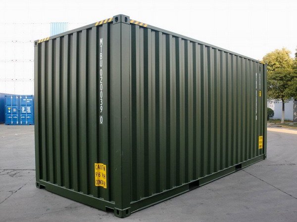
The Container

The core structure comprising the home is a 20 foot long shipping container of the type seen in any port which carries goods across the sea, and at times, on rail and truck.  These containers come in several standard lengths including 30 foot and 40 foot, however I would prefer the 20 foot because it is lighter, cheaper to purchase, cheaper to build with, and I believe it offers just the right amount of space to occupy.  The internal dimensions are usually 19′ 4″ long, by 7′ 8″ wide, by 7′ 10″ high.  This provides a floor space of approximately 148 square feet.  In order to have space for two occupants to sleep, lounge, bath, cook, and utilize a composting toilet, I would prefer to locate a “High Cube” which has an internal height of 8′ 10″.  The other dimensions are equivalent to the numbers previously stated.

Interior Layout

The additional height allows for a split level configuration, not two full stories of course, but a cozier loft and cubby type configuration.  I do not have any diagrams depicting my design (they’re still stuck in my noodle). so I will do my best to describe it here.  Standing in the middle of the container facing one of the long sides, to the left would be loft area approximately 3.5 feet off the floor, extending from the short wall out to 8 feet, and from long wall to long wall, comprising an area of 61 square feet.  This loft area, unlike many tiny homes, would not be the bed but would rather be the lounge area with couch, cushions, computers, viewing screens, and the like.  The area beneath the loft would be the bed where one would find a shallow queens sized mattress.  These two levels could be switched, with a loft level being about 3.5 feet from the ceiling and the bed being up there, but I think I would prefer the lounge being higher in the structure so a better view can be appreciated from wide windows installed high on the side of the structure.  Access to the loft area could be accomplished by a ladder or preferably a large stepped storage structure built in somewhere.

Again, standing in the middle of the container, facing the long wall and looking the towards the other end, another split level configuration is employed for the kitchen and bath.  Unlike the lounge area, this platform is only 2.5 feet off the floor, and extends from the short wall out to about 8 feet, comprising another 61 square feet.  The exact orientation and placement of the kitchen and bathroom is not yet known, only that a bathroom sink will not be needed, and the placement of the shower and kitchen sink will be quite near to one another in order to minimize plumbing needed and to maximize water pressure and hot water temperature.  Toilet facilities are accomplished with separating composting system.  This could really be placed anywhere in the house since no fresh water or drainage is needed, but it most likely would remain a part of the shower in some way.

The space underneath the kitchen / bathroom platform would have the main purpose as an engineering / utility space.  This would comprise of an on-demand LP water heater, RV style fresh water tank with 12VDC pump and pressure tank, a grey water receiving tank for heat recovery, radiant floor heat equipment (if employed), battery compartment with outside ventilation, solar / wind charge controller, power inverter, breaker / fuse panel, and any other system that can be placed here for easy access.  The remainder of the space could be used for storage with access for everything being from a liftable hatch in the floor or similar assembly.

The entryway is placed in the middle of one of the long walls and is likely to be a full glass door to admit as much light as possible.  Above the doorway is a window for yet more light.  A wide window is placed in the lounge area on the end short wall, the long wall, or both.  A few more small windows might be placed in the kitchen area, and a well insulated translucent window in the shower.  Skylights and solar tubes would be nice, but likely will not be used due to concerns about possible water infiltration.

Insulation

The issue of insulation is a tricky matter.  Commonly, shipping container homes are insulated on the interior walls with spray foam, rigid board, or fiberglass between wooden studs.  I shy away from these methods because of these materials environmental impacts.  I could employ less toxic, lower embodied energy insulations on the interior walls, leaving the rugged steel shell exterior for a more industrial look, however I find the notion of insulating the inside to be a waste of floor space, and the level of thermal insulation I desire would make the inside of the container much smaller than it already is.  The other problem, much more serious, is that by leaving the steel shell exposed to the outdoor environment, indoor humidity generated from daily activities could condense against the inside wall of the steel on cold days, leading to mold and rot of wooden members or decay of insulation.  Another concern with an uninsulated steel shell has to do with the thermal mass of the steel box and the possible tendency for it absorb heat on a warm sunny day and not only cook the occupants inside while the sun shines, but also a lag effect might prevent the interior from cooling off at night sufficiently.  For these reasons and others, I’m opting to insulate the exterior.

Many super-insulated homes utilize a double exterior wall made of two 2×4 studded frames as much as one foot apart.  At a certain point in the construction, the cavity is filled with high density blow-in cellulose insulation.  By building two walls, the thermal bridging effect is avoided because the interior studs do not contact the exterior wall sheathing directly.  Thermal bridging still occurs at the top plate, bottom plate, and around windows and doors.

I’d like to draw on this idea of a very thick wall, but simplify it a bit.  Since the shipping container already represents the interior wall surface, I would like to essentially build a big wooden box around the smaller steel box.  The base of the structure is a series of 4×4 or 4×6 beams on which thick marine grade plywood would be screwed out to the perimeter of the finished platform.  How exactly the container would be supported, I’m not sure.  I need to gain more experience with framing.  One possibility is that a knee wall would be built with beams set across which the shipping container would be bolted to, leaving a foot of space underneath for insulation.  On the top plate of the knee wall is a studded wall with plywood sheathing on the exterior.  The foot or so between the wall and the container is filled with cellulose.  The wall would support a steel roof set to a slight pitch for rainwater catchment.  Enough space is left between the top of the container and the roof to allow for at least R-50 worth of insulation to be blown in, and still have sufficient air space for ventilation to keep everything dry.  The top of the container might be firmly anchored to either the roof structure or to the walls near the top.

I considered straw bale insulation for a time.  I have no experience building with the material, but I’ve researched it extensively.  The biggest issue I can see with straw bale walls is that typically they are plastered on both the interior and exterior with an inch or so of earthen or lime plaster.  This gives them a great deal of strength.  Butted up against the shipping container, I can’t see how I could really achieve this.  Also, I think that blow-in cellulose would just be much easier.  One idea that still nags at me, is making a bed of straw bale on the base wooden platform which the container would simply sit on.  I have little doubt that the bales could effectively support the box and also provide a great deal of insulation.  Issues with rot and rodent infestation concern me, but I’ll continue to consider it.

Facade

As far as the exterior finish goes, I haven’t really thought too much about it.  I’ve always liked rough lap boards.  Probably some kind of wood finish in the interior as well.  I’ll figure that out later.  Form follows function, right?

Thermal Mass

This last bit is one of my favorite topics when it comes to housing.  The steel of the shipping container, fully enclosed in an envelope of insulation, can provide the function of a thermal store of heat.  By absorbing and releasing heat, the steel serves to damper temperature swings inside.  I don’t think that 5,000 pounds of steel is small potatoes when living space is less than 160 square feet and the thing is super-insulated.  I really don’t know for sure, but I feel that the design as I’ve described it would be quite easy to heat and cool.  This is where it gets a little weird.  Water bottles.  Yes.  By building up the floor of the shipping container and lining the subfloor with a layer of used water bottles, full of water, I could reasonably add over a thousand pounds of water thermal mass to the floor.  If I chose to install radiant floor heat, I could run the plastic lines back and forth under these bottles, allowing the system to be charged up with heat which might even out the heat distribution in the floor and hold it over a longer period of time.  SImilarly, before installing the insulation, I could find a way to stack up water bottles against the exterior surface of the corrugated steel walls, thereby adding passive thermal mass to the walls.  Hell, I could even line the whole roof of the container in water bottles.

Miscellaneous

There are many other issues to discuss, but this article is getting really long, and I do not yet have any drawings to accompany my ramblings.  A few last things.  Because the house is designed with a shipping container, some means by which to provide fresh air are necessary.  Beyond openable windows and a ventilation fan, a heat recovery ventilator would be a good idea too.  I think I would want to install inspection ports in the the walls and floor to check on the moisture levels in the insulation and make sure things are staying dry.  I don’t think a vapor barrier is going to be necessary since the shipping container steel walls would keep most moisture from migrating through the insulated wall, other than around windows, doors, and vents.  Some sort of access to the attic space for inspection would be wise as well.

So far, the design seems like it would sit best on a well draining gravel bed, if not slightly raised on blocks.  It would be nice to have a structure which could be loaded onto a trailer and moved without it falling apart.  I’ll think about that one a bit more in the future.

I’ll keep doing my homework, and get to making some drawings.  Ta!

-M.C. Pletcher

Tagged with: , , , ,
Posted in The Squatch

Determination and Resolve


I feel a little lost lately.  I’m still looking for a cause to devote myself to.  It’s not like there aren’t enough options; the list of interests I have is endless, but I have little structure in my life to see anything come to fruition.  I’m living in a motorhome right now as a step towards taking control of my life and finding a place to call home.  At one time, I planned on buying rural property to build an off-grid, naturally constructed where I could free my time to focus on whatever the hell I wished to pursue.  However, those plans changed when we realized that the rural environment we grew in wasn’t fulfilling enough, other than close friends and family.  We wanted something more, and like so many folks have been doing, we moved to Portland.

Our decision to move 2,700 miles across the country and settle in a small city has been positive overall.  With my lack of formal education, I have slipped into yet another dead end job in an industry I despise, and with coworkers that, to put it mildly, don’t resonate with me.  This, I must change.  Even a lower paying job where I can contribute to a cause I deem worthy, would be a positive change, but alas I have not made such a move as of yet.  So much of my time is lost to renting my labor, and it seems the remainder is spent stressing fretting over the tyranny and unscrupulous practices of society at large.

I have found hope though.  Hope in the form of the smiling faces and positive demeanor of fellow Portlanders.  True, it is less common here in Milwaukie, Clackamas County, but I vow to return to the city where a vibe of intentional change is almost palpable.  Expressive people strut down city sidewalks in an environment which breathes calmness and acceptance.  I enjoyed my time in the Richmond neighborhood and I desire a return to a close-in neighborhood, but with a more active role in my community.  I seek community, a place to call home where I can invest my time positively in constructing a home, and helping others do the same.  Many of the technologies that have interested me over the years, as well as the ones I have dreamed up, but never built, I have been unable to implement due to the temporary nature of rental apartments and homes.  I am ready to build– to stay.

I could return home where land is cheaper and my friends and family are, but the culture and opportunities there are lacking, and I am sure I would regret the move.  I truly believe that cities must become the hub of sustainability and innovation where the majority of the population must live in order to give the wild areas the chance to recover.  As far as cities go, Portland has a lot of advantages.  Water is abundant here, and will likely remain so for the forseeable future.  The summers can be hot, but bearable, and the winters are pretty mild.  The growing season here is long, and wild places are locked up in State and Federal Parks all around the area.  In addition to the geographic pros, there is again the culture of optimism and a general political attitude pushing towards social democracy, to the dismay of the surrounding conservatives.

There is much in the world to see, yes, and I hope to travel, but I feel it is my duty to myself and my wife settle down and develop personally.  I have a lot of ideas, some of which might be worth a damn, and I won’t be able to influence others until I stop living so temporarily, always renting and “working for the man”.

The steps I can take now include the development of relationships with other people seeking a community lifestyle in the city, finding a cheaper place to park our motorhome which is preferably closer to the city, pushing myself to improve and advance the development of our home despite my lackluster attitude cultured from my job, and of course, find a new damned job!

These things will not occur simply because I wish them to, they will only culminate through determination and resolve.

-M.C. Pletcher

Posted in Personal

Build A Community, As If Your Life Depended On It


These are uncertain times to be sure.  The human population is almost 7.3 Billion, and as of this writing, the net population growth on Earth this year is about 602,000; yet it is only January 3rd.  I don’t look at these numbers often enough.  Perhaps it would do us all well to have a population counter on display in each town center, to provide a little reminder of the incredible success our species has had over the last 10,000 years.  “Success” is a relative term, I fear, and future generations may not view our explosive takeover of the planet quite so positively. I think it is safe to say that each generation born will consume more resources than the previous generation, on average.  Our massive numbers only represent a portion of the impact we have, as our extractive appetite pushes the planet’s carrying capacity closer to the brink.

(In the time it took me to write this much, 3,700 net human beings were added to the human biota.)

Cause for alarm?  Sure.  Cause for panic?  Panic is never a wise reaction.  In my opinion, stockpiling ammunition is a form of panic, and I prefer to steer clear of these nitwits.  Yet it is also not wise to ignore these startling numbers as well as the calls for action by the world’s leading scientists regarding fresh water supplies, top soil erosion, fossil fuel depletion, biodiversity loss, and of course anthropogenic climate disruption.  There is no simple solution for these ills, only a seemingly insurmountable population wide paradigm shift in the way we metabolize resources to interact with the rest of the biosphere– might avert a fate worse than the famine and population collapse we are blindly sprinting towards.

I can’t tell you what to do about this; all I can suggest is my own plan as of this writing.  My plan is to have a good life, rich with experiences and good relationships with people I trust and care for.  I’m not a nihilist.  I’m not running up the white flag and giving up all hope so I can justify ignoring the truth and flipping the bird to future generations!  Quite the opposite, in fact.  The truth is, in my 28 uneventful years on this rock, I’ve observed that life is more bearable, and more fruitful as community– rather than as individuals.  Surprised?  I doubt you are, because most cultures seem to view family and community with high prominence.  What changed?  Consumption oriented propaganda?  An economically competitive culture?  Commercialization of relationships?  I’ll leave you to draw your own conclusions.

Could it be that the hippie commune experiments of the 60’s and 70’s were on the right track?  Perhaps they weren’t always well planned or successful, but some survive to this day, advancing permaculture techniques, organic farming, natural building, community projects, shared resources, and fostering an attitude of respect for self, community, and planet.  Many, many more communities have sprung up since then, building on what did, and did not work in the past.  These are both rural and urban, with the vast majority out in the sticks where permitting and zoning is a bit more lenient.

I’m a fairly pragmatic guy.  I like things that serve multiple purposes, are simple, and beautiful.  In the last few years I have been highly interested in constructing my own home, and after abundant research, I find that some of the most economical and energy efficient construction techniques are also the most ecologically sensible, long lasting, and beautiful.  There are many examples of this in permaculture, which should not be surprising considering the web work of relationships found in natural systems, of which the practitioners of permaculture seek to understand, mimic, and contribute there to.

A society of cheap, abundant energy allows us to live solitary lives which does not necessitate meaningful relationships with the people around us, other than for recreation, but even relationships can be bought nowadays.   How do you plan to get by when the cheap energy is gone, the financial, commercial, and political systems have collapsed?  I know what I’m doing before it gets much worse.  I hope you will join me.

(14,000 people in the time it took to write this piece.)

-M.C. Pletcher

Tagged with: , , , , ,
Posted in Dwelling, Personal, Philosophy

Creating Affordable Housing in Portland


There are many reasons for wanting to live in a city as beautiful and progressive as Portland.  For us, we like the fact that by staying close to the city core, we don’t have to commute for our jobs which are in the very heart of the city.  My days at my current job may be limited, but future jobs are going to be in the same area.  Why?  Because I want to work where I live, I eat, I drink, and where I find the most progressive people:  my friends and comrades.  Renting or buying a house can be very expensive in the inner region of Multnomah county, and in order enjoy my life without spending a large portion of our income on housing, I want an alternative.

Group Housing

Increasingly, many younger folks are piling into group houses to live a bit cheaper while also experiencing the benefits, and downsides, to communal living arrangements.  These situations are still on a rental basis, and can be surprisingly expensive for the minimal accommodations.  I suppose this trend towards group living is partly social evolution, but more likely is market driven as real estate values continue their dangerous rise.

Land Trusts

Non-profit organizations such as Proud Ground, here in Portland, offer below market rate houses to working families in the area through something like a limited equity arrangement with the company.  It allows people to own homes they would otherwise be unable to afford, and also ensures that when they decide to sell, the home remains affordable to future potential homeowners.  Community land trusts around the country have been doing similar work for decades, Read more ›

Tagged with: , , , , , ,
Posted in Dwelling, Personal, The Squatch, Tiny House

Enter your email address to follow this blog and receive notifications of new posts by email.

Join 325 other subscribers
%d bloggers like this: