In Part I, I shared a lot of media relating to my efforts in building a refrigeration test bench. I intended to build the whole thing from a DIY approach, and utilize a York 210 – Belt Driven Air Conditioning Compressor. I did some testing with a water cooled condenser and a dry type evaporator in a pale full of water.
In Part II, I try to explain the theory of design, and method of building my gravity flooded evaporator, or “Ebullator”. In this post, I will share some of the more recent media, and initial observations, regarding the Ebullator performance, compressor issues, and the next steps I’m taking to model the system.
 This is a photograph taken just prior to the first run of the ebullator. The rest of the system is the same as before. The propane was charged as a vapor, into the suction line until a steady liquid level was observed in the ebullator sight glass, and a smooth sound was heard from the throttle. The suction line insulation is not yet installed, nor are the four thermocouples. The ebullator rests on a square of reflective foil insulation and 1.5″ of extruded polystyrene scrap I had. I’m building a crude insulated box around it.
 This is when the first tests began. As you can see, I surrounded the ebullator with a simple box of reflective foil insulation. The platform underneath is larger to support the polystyrene insulation which will be added later. I was quite anxious to test it, so I went ahead and charged the system.
 With what few pieces of polystyrene I had from a dumpster dive, and some ductwork reflective tape, I finished the box, with the exception of the top. At one point, the air temperature in the bottom was at -36 degrees Fahrenheit.
Things change a bit from here on. From the start, I wanted to construct my device with an open drive compressor, so that I could choose the power source as well as the operating speed. I became aware of the York 210 automotive air conditioning compressor from a friend, and after considerable research I decided to retrieve my own from the local junkyard. I was having so much fun with the thing that I went out and scrounged for three more; each one having slightly different features, configurations, and quality. I intend to use some for various modifications I have in mind.
What I have found in working with the York that lubrication appears to be the primary problem. Once I wised up, geared down, and made a smoother running test bench for the York, I find that the slow RPM of perhaps, 60 to 120 RPM, is not providing sufficient lubrication to the internal mechanism. In other words, the damned thing squeaks and bangs a lot. Because the York relies on splash lubrication from the crank case, I believe that the low RPM is not picking up enough oil from the bottom of the crank case, and components are rubbing dry, especially the piston seals against the cylinder walls. This last point a a particular concern, since lack of an oil seal will allow gas bypass around the cylinder, and lead to a serious decrease in volumetric efficiency.
I have run both pharmaceutical grade mineral oil from Wal-Mart, and a mineral oil blend purchased from a local refrigeration supply house, the latter of which was designed for hydrocarbon refrigerants. I have heard no difference in compressor noise.
Additionally, I have put two different compressors to work, and their apparent performance appears to be roughly the same. I have been filling the crankcase with the manufacturer recommended volume of oil, and this may need to change if I hope to utilize these high displacement compressors for such a small load. Although I have yet to add more oil as of this date, I think I will give it a try at some point.
A concern with adding more oil, is the high miscibility of propane in most lubricating oils. This fact leads to a severe reduction in the viscosity of the oil, the lubricating effects, and finally loss of thin film oil seal around the piston. I may need a higher viscosity oil, as well as some sort of oil separator to prevent compressor oil from migrating about the system, decreasing heat transfer and and being lost in the bottom of the ebullator.
And so, it was decided to change course for now, and focus on collecting data to model system performance, so that I can determine what the volumetric efficiency of the compressor is, and how it changes with various alterations. In line with this thinking, it was decided to employ a fully hermetic compressor from a small appliance for longer, quieter running times, until such modeling can be made with some degree of reasonable findings.
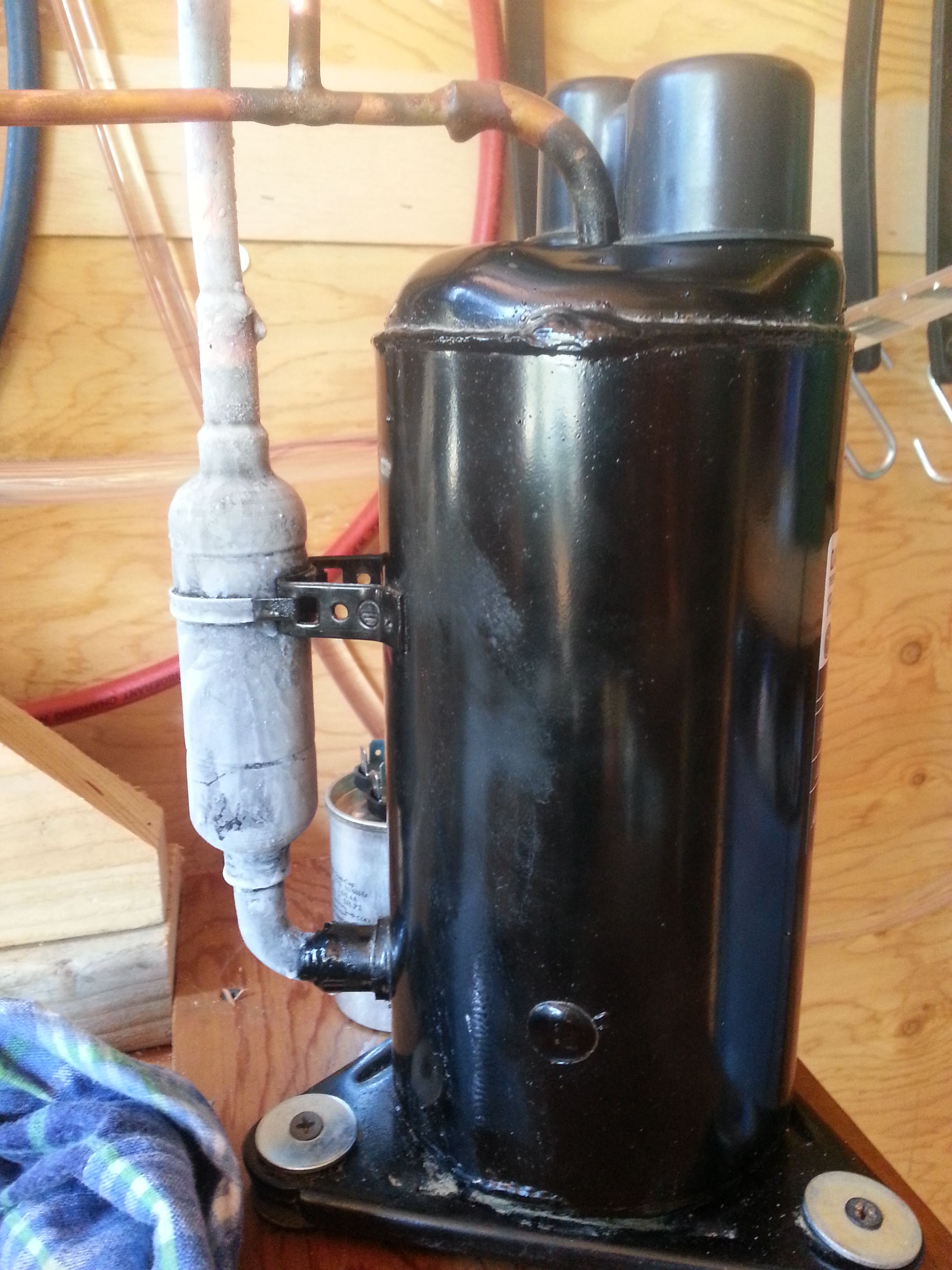
The compressor I chose was salvaged from a 5,000 BTU/hr air conditioner. It is a rotary unit, approximately 1/3 HP, and has proven to be quite a fun little pig to play around with. I had to modify the inlet and outlet connections to adapt to my existing lines so that I can easily swap the York back in when I decide to, with little fuss and short down time. I added service ports, but no service valves at this point.
The system goal from the start, was to build a pedal powered ice machine. In order to accomplish this (if I ever do), I need an evaporator coild which will absorb heat from a quantity of water and lower the temperature to solidification. I’ve considered utilizing a lowering freezing point brine to cool cans of water which will form ice. I’ve since decided, that although that make be an effective method when producing ice continuously and on a large scale, a small batch produced in an hour would be more productive if unnecessary cooling, like that of the brine itself, were not being performed. For that reason, I will likely be pursuing a flat plate heat exchanger with aluminum ice cans. Because of the insulating properties of water ice, the temperature difference between the evaporator refrigerant and the water to be frozen becomes excessive once a thick ice layer forms between, so it is important to keep these ice plates rather thin with cooling coils on both sides.
The design of this ebullator was made for ease of construction, and to observe the real world operation of a gravity flooded evaporator. The results have been positive. As I expected, the suction temperature is always at or near saturation for the pressure of the ebullator, regardless of the throttle position. This should be apparent, since the construction of the device includes a separator (suction accumulator) directly in its design. This more or less ensures that suction vapor is not superheated in the lines of the device, with the exception of the short passage back to the compressor, and any motor cooling within the hermetic shell itself.
One notable drawback of the device is the limited viewing window afforded by the single sight glass in an accessory line communicating with the separator. In actual operation, the degree of thermosiphoning occurring in the evaporator coils (see Part II), is difficult to infer. A feature of the next ebullator design will include a provision to see any carryover liquid refrigerant spilling back into the separator.
Although the needle valve, which acts as the refrigerant metering device, has served me well to this point, it too has limitations. “Needle Valve” is a bit of a misnomer since the restriction is accomplish with a small brass cylinder, champhered slighly, and a corresponding valve seat. In practice, very slight adjustments to the valve correspond to large changes in suction pressure; the range of which is less than a quarter turn. A different valve is necessary. At very low suction pressures, I’ve noticed very bad leaking to occur around the valve packing. This becomes especially severe when the machine is shut down at this low pressure, the pressure equalizes in the system, followed by substantial leaking. I assume this is due to contraction of the o-ring valve packing or something similar. The next ebullator may employ a hermetically sealed electronic expansion valve which can be controlled digitally. I’ve also out a lot of thought into exploited the operation of a thermostatic expansion valve to act a sort of float to automatically regulate the liquid level. Some sort of manual bypass will likely be used as well.
Today, I’m testing some thermocouples I epoxied into some brass tees, to be later installed in the refrigeration lines. These will allow me to measure the temperature of passing refrigerant directly without the accuracy problems associated with taking surface temperatures on the copper tubing.
Much more to come!
-M.C. Pletcher

Please wear full face protection when using that hermetically sealed compressor with R290. The AC motors inside of those are “open windings”, meaning that they assume that the refrigerant is completely inert, dry, O2 and water free. If anything is the slightest bit wrong with the refrigerant, there can be arcing and it won’t be pretty.
Your original idea of using an automotive style compressor with an external belt drive is actually much safer with organic refrigerants.
I would have to disagree with you there, Harry. Yes, a face shield is always a good idea when working with two phase substances under pressure, but I wouldn’t expect the propane to ever combust due to an electrical failure within the compressor. The amount of oxygen necessary for combustion is far in excess of any conditions which would be likely in my systems. These machines are evacuated, then operated under pressure greater than atmospheric. Oxygen is a very unlikely component, especially in the proportions required. An electrical failure, arcing, or over-heating, could lead to a breakdown of propane, due to excess heat, but shorter hydrocarbon chains and Hydrogen need oxygen to burn as well.
If you need other assurances, look into the use of hydrocarbon refrigerants in Europe and elsewhere. The only real danger with propane, is an excessive release in a confined space, with an ignition source.
I enjoyyed reading your post