This post is going to be a bit long because it will be largely media, since I’ve done no writing for the last several months and have been busy in my shop. I will let the pictures and videos do most of the explaining. Also see: Part II, and Part III.
This project was intended to evolve and that is exactly what it has been doing. I have many goals, but not the time to write about them all. My fingers don’t move as fast as my brain, and I quickly grow weary. The videos are a valuable way in which to demonstrate and explain a process, albeit in a chaotic and disorganized way. Nonetheless, I find that in order to document my progress, this is the best tool available to me as the machine evolves weekly and sometimes daily.
 Here I have a lineup of refrigeration compressors from various models and years of automobile. These are York compressors. They are belt driven and utilize a clutch and coil to engage the v-belt to drive the units. They were used widely between 1958 and 1991. Two piston, 180 degrees out of phase, 169 cc displacement. The oil is kept mostly in the crank case, and is not designed to circulate about the air conditioning system. Most commonly used with R-12 “Freon” and mineral oil. E-mail or comment if you need a list of automobiles which used these.
 Here you can see the earliest attempt at driving one of these beasts. The motor is a 2.25 HP direct current model with a PWM controller from a treadmill. I quickly found the motor did not have sufficient torque at the speed I desired. Notice the tachometer reading.
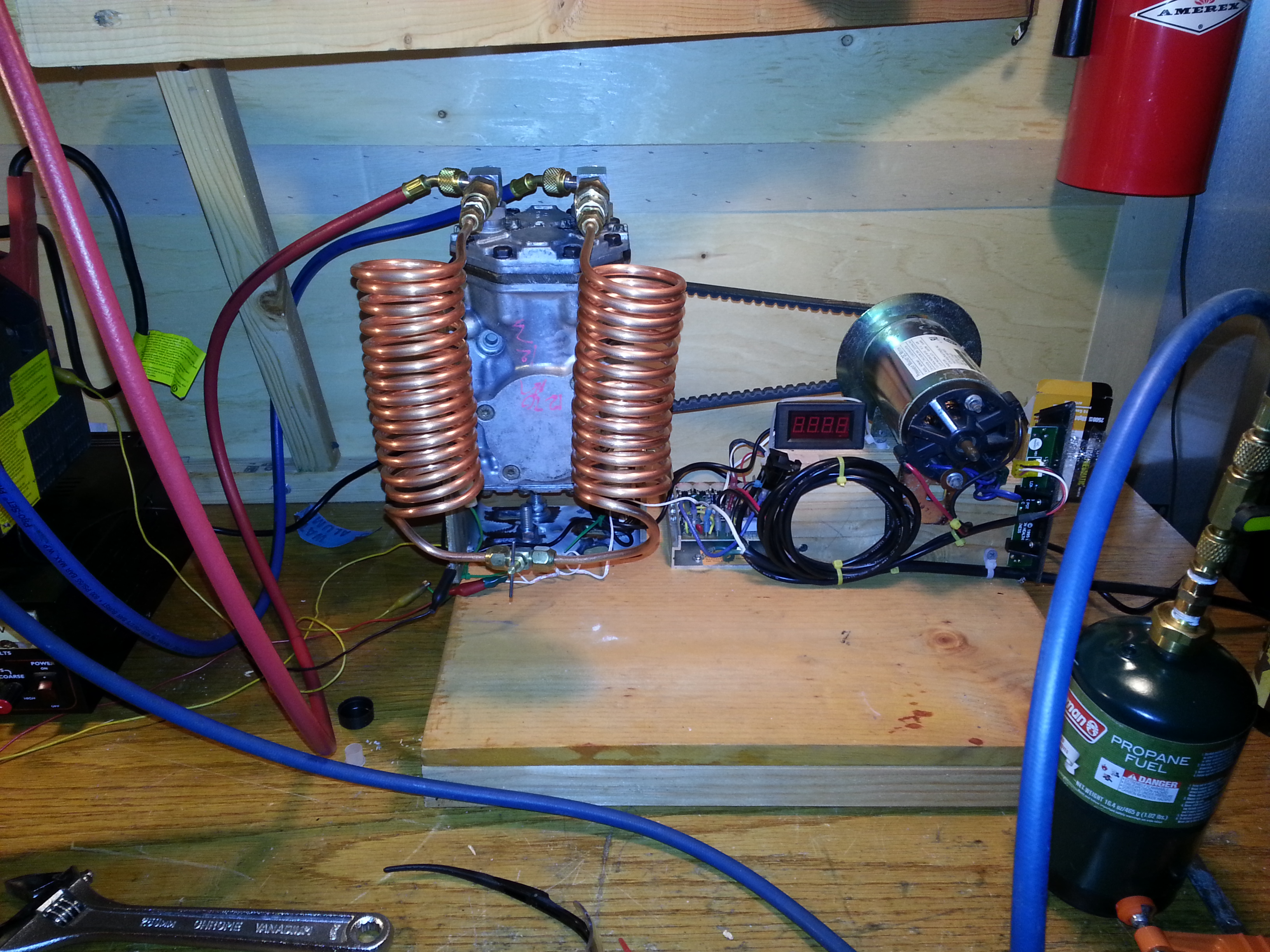 Again, but with a simple refrigeration circuit and needle valve as a throttle. The refrigerant is propane.
 Some gearing down with belts and pulleys, and a crude water cooled condenser.
 The addition of a wooden flywheel constructed of two pieces of 3/4″ plywood made round on a makeshift router table.
 The Mark II refrigeration test bench. This one was designed from scratch in order to provide a sturdier platform for the vibration encountered from the poorly balanced flywheel, and provisions to adjust belt tension and alignment.
 Another view of the test bench. Notice the adjustable alignment / tension blocks for the pillow block bearings.


A 1/4″ copper tubing coil made for the purpose of a water cooled condenser.
 The inner construction before final assembly.
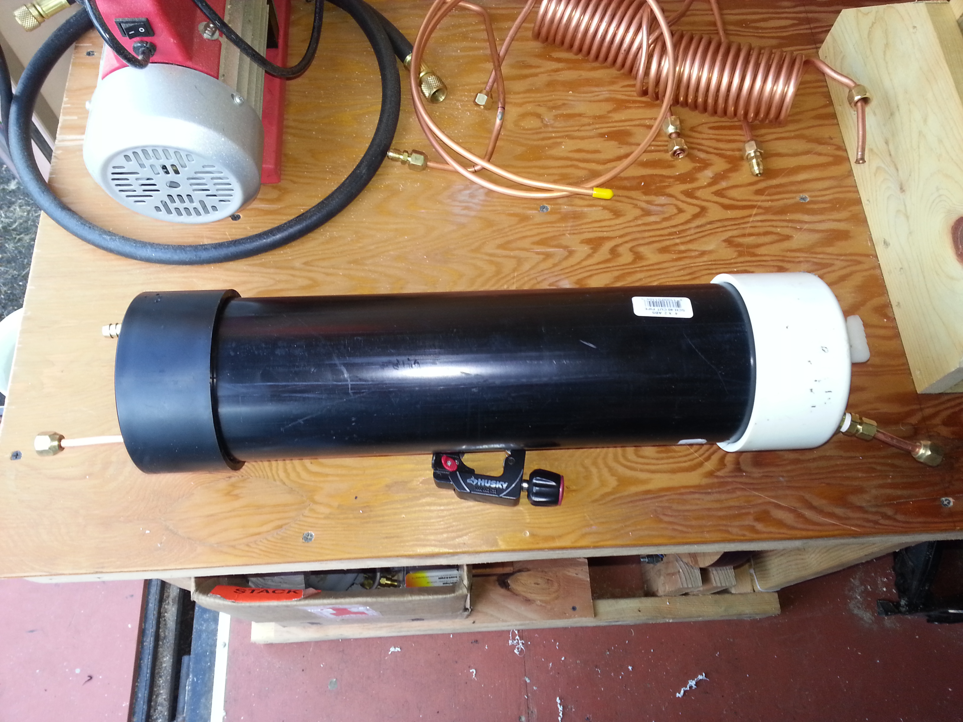 The finished water cooled condenser, designed for counter current flow.
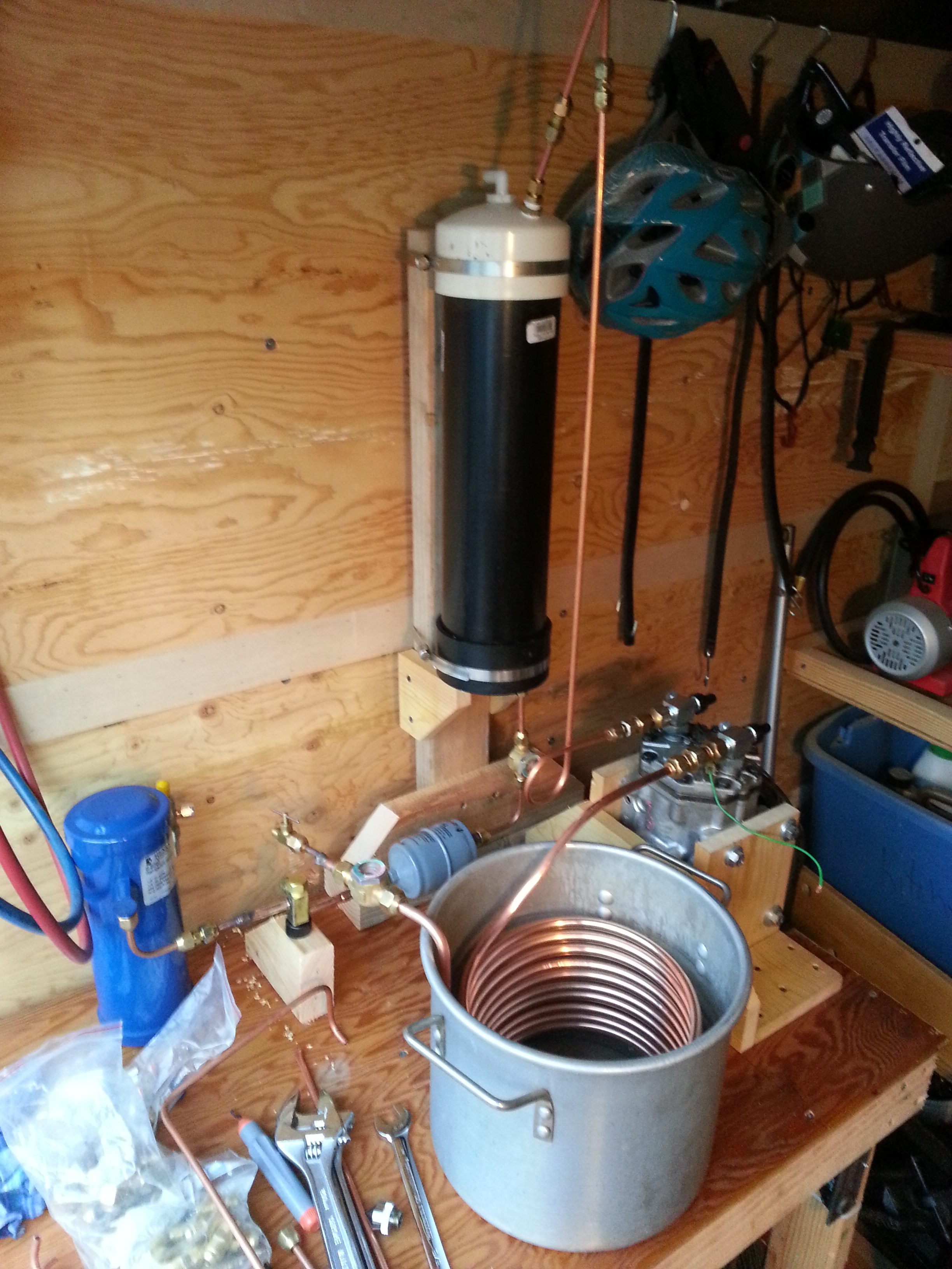 Almost ready for first run. High pressure vapor refrigerant enters at the top of the condenser, and drains off as liquid at the bottom. Cooling water will enter the bottom, and exit the top. A sight glass shows the flow of the liquid propane, followed by a filter/dryer, a service valve, a liquid receiver, a missing line yet to be made, a needle valve refrigerant control, a sight glass to observe quality of refrigerant exiting the throttle, a length of 3/8″ coil, forming a dry type evaporator, and then a return to the compressor at the suction port.
 The apparatus after it has been in use for some time. Notice there is no insulation around the metal pot; it absorbs heat like mad. Also, the ice formation on the coils is interesting to observe, but it effectively insulates the evaporator coil from doing further cooling work. Thermocouples are placed around the system to monitor temperature changes in the refrigerant and to infer the performance of the condition. At the time of this writing, there is no data logging yet occurring.

 The last shot of the dry type evaporator before it was torn down. Some old antifreeze was used to lower the freezing point of the water and make it into an effective brine for freezing bottles of water. Some blocks of polystyrene insulation were used to insulate the thermocouples to get more accurate readings. A crude insulating towel was wrapped around the pot to prevent condensation.
At this point, I had enough from the dry type evaporator coil and began planning the gravity flooded evaporator I would later call “The Ebullator”. I will continue outlining my progress in Part II, and Part III.
-M.C. Pletcher

[…] a system with a large ice storage means where systems that require cooling can dump their heat. A vapor compression pump could be coupled to the flywheel of the main drive, and be made to pump heat from a large insulated vessel of water, making ice. […]