Now that we’ve covered the desire to build a well insulated refrigerator and freezer, as well as the advantages associated with living in a cold climate where ice can be produced passively, it’s time to move on to the detail of what a refrigerator system might just look like, and talk abut ways in which the idea can be expanded to improve the performance of actively powered freezers.
Two-Phase Thermosiphons (TPTS)
First, we have to talk about the operation and principles of a TPTS, and the difference with a Heat Pipe. Both of these devices are forms of heat conductors. Heat naturally flows from regions of a higher temperature to regions of a lower temperature. Metals are a common choice for this- copper and aluminum being two of the more commonly selected, although other metals can be used depending on the environmental conditions present. Metals are well known as effective conductors of heat, but the larger the distance between the heat source and heat sink, the larger the temperature difference necessary in order to conduct a given heat load. Many applications, such as the cooling of integrated computer chips, require the lowest temperatures practicable at the source of heat, and the distance to the heat sink can be a few centimeters, to even more than a meter away. Metals alone are not always suitable, so other methods have been developed.
Counterflow TPTS
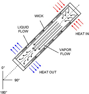
A sealed metal pipe (assumed copper from here on out) containing a a volatile refrigerant at saturation, can conduct heat far better than the metal alone. A simple example would be a one meter copper pipe, sealed with a few grams of r134a refrigerant inside. In a slightly vertical orientation, heat applied to the lower end of the pipe will first be absorbed by the copper, and then conducted to the the liquid refrigerant that naturally settles there. Some of the liquid evaporates, raising the internal pressure of the pipe. Refrigerant vapor higher up in the pipe, now at a higher pressure, will warm to a temperature slightly greater than the copper walls which are cooler than are found below where the heat is applied. The copper walls absorb some latent heat, and the vapor is condensed, falling by gravity back to the bottom, where it can pick up heat and begin the process again. Localized pressure differences between the heating region and the cooling region cause vapor to move from hotter to colder areas. The more of the un-heated pipe which is exposed to the ambient air, the lower the temperature it will reach, and the lower the overall pressure the pipe will reach. If only the top few centimeters are to dissipate heat (the condenser), the middle section can be insulated, such that very limited heat is dissipated in this region (or adiabatic region). By adding additional heat exchange surface area to the condenser end, passing air or another cooling fluid across it, the heat source can be held at a lower temperature than it otherwise would without the additional design features. Also, the surface area of the heat source region (or evaporator) can be improved with added fins, and increased internal surface area- conducting heat into the liquid more effectively and with a smaller temperature difference.

The device is a Counterflow Two-Phase Thermosiphon. Two phases (vapor up and liquid down) flow in opposite directions in a common pipework. They can interact with one another, impeding smooth flow, and increasing the temperature difference (delta T) the device operates at for a given heat load and operating conditions. Gravity is essential for good operation, and is why these are sometimes referred to as Gravity Assisted Heat Pipes. They only work if the condenser region is higher in elevation than the evaporator (unless rotary motion is used). All have a minimum angle for effective operation; too shallow, and the evaporator can “dry out”.
Heat Pipes
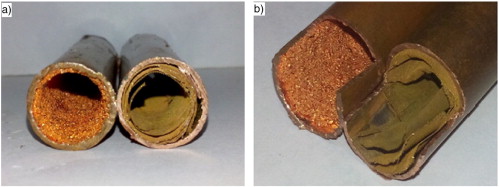
A genuine heat pipe is similar, but it differs in one crucial manner: It can move heat regardless of gravity. By using a surface area enhancing internal structure made of copper felt, copper screen, grooved channels, and most often as sintered metal, they can return condensed liquid to the evaporator by capillary (or wicking) action alone. Gravity can play a part, but they are designed such that they can usually move heat sideways or down, although they may just as likely be used where a TPTS would work too. Heat pipes have the advantage of separating the vapor and liquid flows, leading to increased performance. The enhanced internal surface area improves evaporation without excessive super-heating of the liquid, and improved condensation at the condenser. They have a wide variety of applications where they are well suited, but the methods to produce the enhanced internal structures, and the high degree of internal cleanliness necessary, make them difficult for home manufacture. They won’t be discussed further.
The distinction between TPTS and Heat Pipes is important, but the terms get mixed around a lot. A wick structure for liquid return is the main distinction. TPTS can use enhanced internal surfaces to improve performance, but liquid return remains dependent on gravity, so it remains a TPTS.

Other Types
There are many more variants on the two-phase transmission of heat, and if the reader is interested, there are pulsing heat pipes, capillary pump loop heat pipes, one-way heat pipes that won’t conduct heat in reverse, methods to set conducting temperatures, ways to limit conducting heat flux, the “Copper Cricket” geyser pump, and the most DIY friendly: Loop TPTS.
Loop TPTS
All two-phase heat conductors are a form of “heat transformers”, in the sense that they are designed to couple the heat of one medium, over a certain area, to that of another medium, over a certain area. In the case of cooling heat producing devices such as silicon chips, a small surface area load is to be cooled by the ambient air, so a rather large heat flux on a small area (high heat flux density) is coupled to the most air possible, by using an increased surface area on the condenser, and an active fan. In this way, the heat flux is “spread out” across many molecules of atmosphere, with a small temperature rise on each. Coupling to less cooling medium would result in a higher temperature rise on each molecule, a higher condenser operating temperature and thus pressure, and finally suppression of vaporization in the evaporator (higher source temp).
Generally, the greater the amount of surface area on both the evaporator and the condenser, and the less pressure drop through the lines, the better the coupling of the two mediums.
Overview
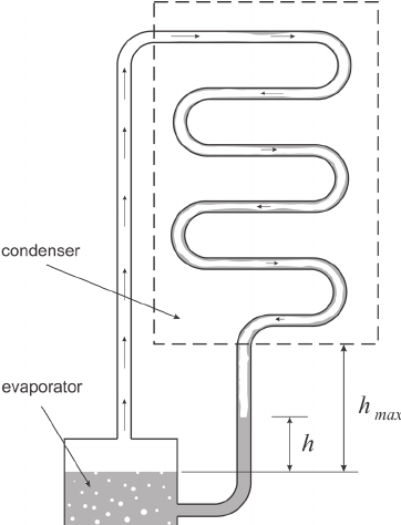
In this type, all the principles of a Counterflow TPTS remain largely the same, except we separate the rising vapor from the falling liquid by building it as a continuous loop. Gravity is of course the means of liquid return here, so the evaporator must be situated below the condenser. Vapor produced in the evaporator rises through the riser to the top of the condenser by the lower temperature and pressure found there, and the condensate that falls through it collects and returns through the liquid return or downcomer to the evaporator. Vapor is prevented from reverse flowing through the downcomer by constructing the return in such a fashion that a liquid plug is formed near the evaporator. This is often done with a simple P-trap before the evaporator. Like any two-phase heat conducting device, a slight pressure difference exists between the evaporator and the condenser. The degree of this delta-P is evident in the amount of liquid head supported in the downcomer, before the trap, and can be expected to be a few millimeters to centimeters. Depending on the delta-T the device exhibits given a certain heat load, the pressure/temperature relationship of the refrigerant chosen, and the density of the liquid at that temperature in the downcomer, the head can be calculated. Directly observing this head is not critical for designing the system (although it could be useful); it is only important to ensure a proper liquid plug for smooth unidirectional operation. The P-trap could be unnecessary if sufficient liquid is always covering the exit of the downcomer.
Piping and Refrigerant Choices in Loop TPTS
Certain considerations need to be made for the tubing sizing in a Loop TPTS. Depending on the refrigerant chosen, a narrow riser could cause excessive friction to the rising vapor, if the density of the vapor is quite low. Methanol and water refrigerants are a good example of this; they have rather large specific volumes at temperatures near the human habitation zone. Because the mass flow in all parts of the system are the same, given a certain heat load, a low specific volume could produce excessively high vapor velocities in a narrow riser, leading to extra pressure drop between the evaporator and condenser. This translates to a larger delta- T since a higher temperature needs to be reached in order to raise the pressure enough for the vapor to pass through the riser and into the condenser, where it condenses at lower temperatures. A larger riser tube diameter (and few sharp elbows) ensures a smaller pressure difference (and thus smaller delta- T) to carry a given heat flux.
Other refrigerants may be more suitable for a certain operating temperature range. With higher temperatures such as a computer chip or a water heating scheme, water or methanol may be a good choice, as they have high latent heat of vaporization, and the smaller specific volumes at these temperatures. High pressure refrigerants tend to have higher density in vapor form, and thus a given riser tube diameter results in lower vapor velocity, assuming mass flow is the same. Mass flow is also dependent on the latent heat of vaporization characteristics of a refrigerant. Water (~2257 kJ/kg), Ammonia (~1369 kJ/kg), and Methanol (1100 kJ/kg), all have relatively high latent heat values, and thus require lower mass flow in a TPTS. For a refrigeration application where the pressures could be on the lower end (compared to cooling electronic devices), the specific volume can still be a limiting factor, even with lower mass flow. That is, with the exception of Ammonia which exhibits higher pressures and lower vapor specific volume. Ammonia can be a fantastic choice for a low temperature TPTS, but special considerations need to be made for material choice, as Cupric materials will react, so generally steel, or sometimes aluminum is chosen.
In addition to the low specific volumes of water and methanol vapor at refrigeration temperatures, they must operate in a vacuum, which if a leak were to occur, means atmosphere is drawn in. Non-condensable gases tend to accumulate high up in the device and disrupt flow, as well as inhibiting rapid evaporation and condensation at heat exchange points.
High Pressure, Non-Corrosive Refrigerants
Many of the refrigerants used in vapor compression systems at the operating temperatures of interest (around 0 degrees Celsius and lower), may be suitable for a Loop TPTS. CFCs, HCFCs, HFCs and HCs (hydrocarbons) have all been used at one time or another. R134a is a notable example, being extremely common, relatively inexpensive, and in most regards safe; it is an obvious choice. The Bob English ice refrigerator originally used r12, but later shifted to r134a, due to its more benign environmental effects. Hydrocarbons are another choice, specifically propane and iso-butane. N-butane is an option, but the pressure/temperature rlationship puts the pressure right around atmospheric at 0 degrees C, so it would often operate in a vacuum and have high vapor specific volume. Iso-butane is a bit higher pressure, but could still end up in a vacuum given cold enough conditions.
Propane is my favorite option; it has a relatively high latent heat (~428kJ/kg), common and cheap, the pressure remains positive in all but arctic weather, and the specific volume of vapor should be high enough for reasonably sized riser tubes. Of course with all hydrocarbons, flammability is an issue, but common sense needs to prevail here. The charge size should be as small as practicable, the tubing construction should be well tested to be leak free, and the device should be kept away from sources of ignition. The chances of ignition are very low, if sensible actions are taken. For an outdoor thermosiphon, not passing into a living space, I think hydrocarbons are a great option, and even inside a home, the rewards probably outweigh the risks.
Carbon Dioxide is a very common refrigerant in TPTS used for maintaining permafrost conditions under structures, roads, and damns in Alaska, Canada, and Russia. High strength steel pipe must be used, and quality welds at the joints, as the pressure can be very high. I’m personally very uneasy about the pressure potential of a CO2 system, but if I were to build one, I should think charging it could be made relatively easy by inserting some amount of dry ice in, venting off non-condensing air from a bleeder on the top, then sealing the system off. Not my thing; I’ll stick to lower pressures.
Heat Exchanger Design
Evaporator
The evaporator can be constructed in any number of ways, as long as certain considerations are made for effective separation of liquid from vapor. The vapor should be able to easily pass into the riser, without slugs of liquid inhibiting the flow. Naturally, the inlet of the riser should be elevated above the normal running liquid level in the evaporator assembly. Even a simple cylindrical coil can serve as the evaporator, where the downcomer feeds the bottom, the gradual upward slope of the tubing allows produced vapor to rise towards the top, and pass up the riser to the condenser. Such a design could have inconsistent operation due to slugs of liquid being forced upward, and could slow vapor rise. Variations in heat load might see reasonable operation at lower delta T or heat load, but the internal volume becomes more volatile at higher delta T and heat loads, leading to two phase flow around the system; a condition that will likely continue to carry heat, but is markedly less efficient.
Several smaller coils can be plumbed in parallel, with a common header (or separator), where the phases can be separated by density, with the saturated vapor able to pass freely up the riser, and the un-evaporated liquid to either flow back down the coils in fits and starts, or given a specific return line toward the bottom of the evaporator assembly. This is a feature of the Scott Nielsen ice refrigerator, as well as the Bob English version. The upward flow of vapor and slugs of liquid to the separator tank provides for unidirectional flow within the evaporator loops, and prevents vapor bubbles formed on the interior surface from superheating excessively. Once vapor is formed, there is no sense in it remaining in the heat exchange region; it should travel as quickly, and with the least pressure drop, onto the condenser. Vapor pockets in a calm evaporator displace saturated liquid from absorbing heat, essentially reducing heat exchange surface area. The goal is to form small bubbles, and “flush them away” rapidly. A very tall evaporator, with a high liquid column, can produce a slight increase of pressure at the lowest elevations, exhibiting a larger overall delta T. It is probably not a huge concern, I just wanted to point it out, as it has been noted since the early days of refrigerator flooded evaporators.
Other configurations are possible, including a very shallow coil, or even flat, if provisions are made to effectively separate the phases, and return the liquid. I’m not sure of the exact construction. but many flat loop thermosiphons have been built for maintaining permafrost conditions under northern latitude structures, as it has been found to be more economical than making and installing many sloped versions. Flat plate heat exchangers (HXs) can cool silicon chips, but generally need to be carefully designed to avoid deformation of the flat surface due to the pressure differences; round tubing is much stronger, given the same wall thickness.
Added external fins or other structures can increase the thermal conductance of a HX, without a substantial increase in delta-T, coupling the refrigerant to more of the medium to be cooled, and producing vapor at a lower temperature. Increased internal surface area structures such as felts, meshes, and sintering, have the same effect, but can also alter the boiling regime to encourage nucleation and other forms of vapor production that escape the surface quickly, displaced by saturated liquid. These internal structures are especially useful when dealing with small area/high heat flux surfaces, but any evaporator could probably benefit from them, if it is economic to do so. Passive winter ice production, probably doesn’t warrant the added cost to such enhanced internal structures, and other improvements could be more worthy, such as external surface structures, more tubing runs, and better condenser construction.
Condenser
Many of the same principles apply to condenser construction, as the evaporator. High surface area, both externally, and internally, reduce the delta-T by lowering the temperature at which condensation can occur. Again, the internal structures are probably not economical with a passive winter ice design, but external structures most certainly are. Any way to couple the condenser to as much environmental air as possible will help lower the internal pressure, and remove latent heat from the heat load surrounfing the evaporator. Making use of natural air currents in a generally windy area is also a plus.
The riser should enter near the top of the condenser where some degree of slope of the HXs should carry the condensate downward to the downcomer. Deviations in the slope that could lead to pooling of condensate should be avoided so as to not block vapor from freely contacting HX internal surfaces. A much more vertical orientation may be advantageous as small amounts of condensate should form and quickly fall by gravity, beading up with other droplets, and stream down.
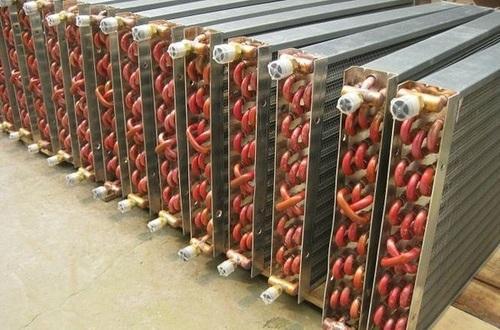
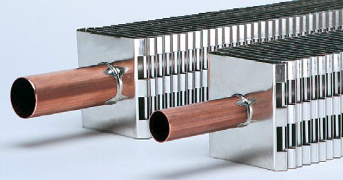
Common refrigerant to air HXs, as are seen in household and commercial equipment, might be used in a passive system like this, but they are not ideal, as they are designed for an active system where the horizontal tubing runs don’t hinder refrigerant flow. Yes, such a HX could work as a Loop TPTS condenser, but it would have to be mounted completely level so as to avoid liquid plugs forming, and the tubing diameter should be large enough that pressure drop is kept to a minimum. Also, many of these HXs are plumbed in haphazard fashions for various reasons specific to a vapor compression machine. Personally, I have had good luck using a brass automotive heater cores for a condenser. The advantage here is the vertical microchannels, as opposed to a serpentine design. I did have some difficulty with the narrowness of the channels, where surface tension seemed to prevent condensate from easily falling. A larger channeled vertical HX would be better.
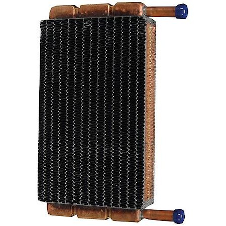
Similar to the evaporator, multiple HXs can be assembled in parallel, where a common header connects them at the top, and a common collector catches the liquid at the bottom to be fed to the downcomer line. Much like the riser tube, pressure drop occurs across every tube, but specifically any tube carrying vapor. Distributing the vapor flow across several HXs at once, as opposed to one long one, helps to reduce the potential delta P and overall pressure gradient in the condenser. A great HX choice would be hydronic baseboard radiator tubes, just like Scott Nielsen and Bob English used. They could be built in any number of slanted, vertical and/or arrayed fashions.
Turbulence and More Pressure Drop
Narrow vapor lines by themselves could be a large source of undesirable pressure drop, because of friction with the internal walls. Every TPTS requires some degree of delta T in order to move heat, and thus a certain delta P. Pressure differences between warmer regions of the device, and cooler regions, results in an increase in the vapor velocity. If the cross sectional area of a tube is narrow, the velocity of the vapor increases, and if the lower pressure region at the outlet has a sudden larger cross sectional area, the velocity of the vapor will decrease, and do so with some degree of irreversibility. In other words, turbulence of the vapor occurs, and a loss of pressure. Had the transition been more gradual, less turbulence and less pressure drop. Generally, changes in cross sectional area should be avoided, but in the real world that is unlikely with a LoopTPTS, so they should occur somewhat gradually if possible. Tight bends should be replaced with gradual sweeps.
All of these irreversible turbulence losses result in minute pressure drops throughout the system, with focus on vapor migration. Aggregated, they increase the temperature at which the evaporator will need to be raised to carry a particular heat load to the condenser. Taken with the thermal resistance of the heat exchange materials, potential superheating and subcooling of the refrigerant in the evaporator and condenser respectively, the presence of flow inhibiting non-condensable gases, and a myriad of other factors, the overall thermal conductance of the device can suffer.
None of this is to say that these devices are necessarily difficult to construct, but if the requirements are very strict, it can get very interesting. With some basic knowledge of the layout of a simple Loop TPTS, a working unit can be seen to work without any specialized equipment. That is the beauty of these things; they are so simple, and anyone with the ability to cut and solder copper could build one.
Up Next
Now that we covered the basics of TPTS, it’s time to move on to some possible designs, focusing on passive winter ice production.
-M.C. Pletcher

Hi, I have been following your videos for a while, and I would like to know if you would consult for on some mini compressors that we want to use on our product.
Please contact me privately.
Thanks