I’ve grown quite fond of the gravity flooded evaporator in the last year or two. It has a number of advantages over a dry type evaporator. I’ve discussed some of these in previous posts (here and here) and I will no doubt reiterate some of them today. First, to define the differences between a gravity flooded evaporator and a conventional dry, saturated evaporator.
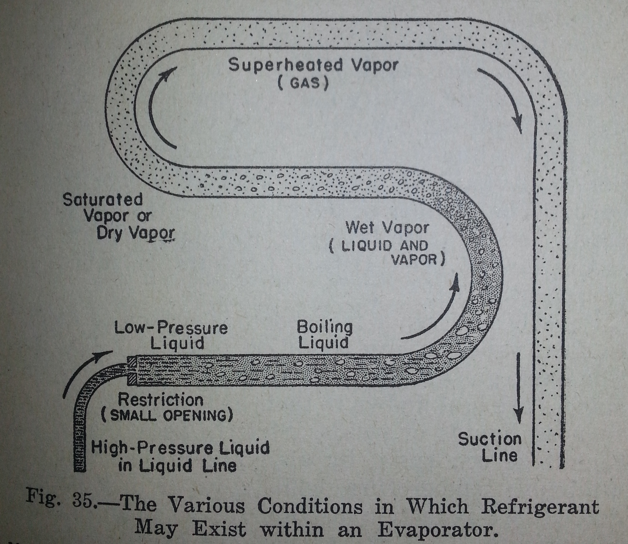
Somewhat briefly; the above is a quite simple illustration of a dry evaporator. Essentially it consists of a passage of tubes or tubes that carry a low pressure liquid refrigerant undergoing phase change admitted through a restrictive orifice of some sort, that creates a pressure drop between the high pressure condensing side of a vapor compression system, and the suction side. As the low pressure liquid is exposed to the warm inner wall of the tubing, it vaporizes and cools the tube or tubes. The chilled tube in turn absorbs heat from the local environment, whether that is air, water or some other medium. The amount of refrigerant admitted into the evaporator must be controlled so that, given the conditions of the system, all of the refrigerant vaporizes without any substantial rise in temperature. If too much refrigerant is admitted, not all of it vaporizes and liquid is drawn back to the compressor where it can cause damage. Both of these situations are to be avoided, but it is more likely that the system will be operated in a slightly starved condition so as to avoid mechanical damage. The superheated vapor has a minimal refrigerating effect and can greatly reduce the overall mass flow rate in the system.
Better system performance is generally seen when the higher suction pressure can be maintained, which means a smaller temperature difference between the refrigerant and the environment. One way this is done, is by increasing the heat transfer surface area. In atmospheric evaporators, heat conducting fins absorb heat more effectively than the tubing alone. Increasing the length of the evaporator tubing also adds heat transfer surface area, which is done in addition to fins and often a circulating fan or pump to move the cooled medium across the metallic surfaces. Unfortunately, increasing the length of the tubing has a very nasty consequence: pressure drop.
Pressure Drop Sucks! (so to speak)
Pressure drop happens and cannot be avoided, as far as I know. It’s what allows fluids to move through a passage; a potential difference. The longer a section of tubing or narrower it is, the more pressure drop will be seen across that length. It happens all throughout a vapor compression system; in the high side, low side, compressor valves, and is of serious concern when designing a system. Across the condenser, excessive pressure drop can lead to higher head pressures than would otherwise be needed for the condensing temperatures. The same goes for a restrictive discharge valve. A restrictive intake valve leads to unnecessarily low compressor pressure on the suction stroke and reduced mass flow. Across an evaporator, excessive pressure drop leads to unnecessarily low suction pressure, an evaporator temperature gradient and sometimes difficulty in controlling steady refrigerant flow into the evaporator.
Anyway, the gravity flooded evaporator…
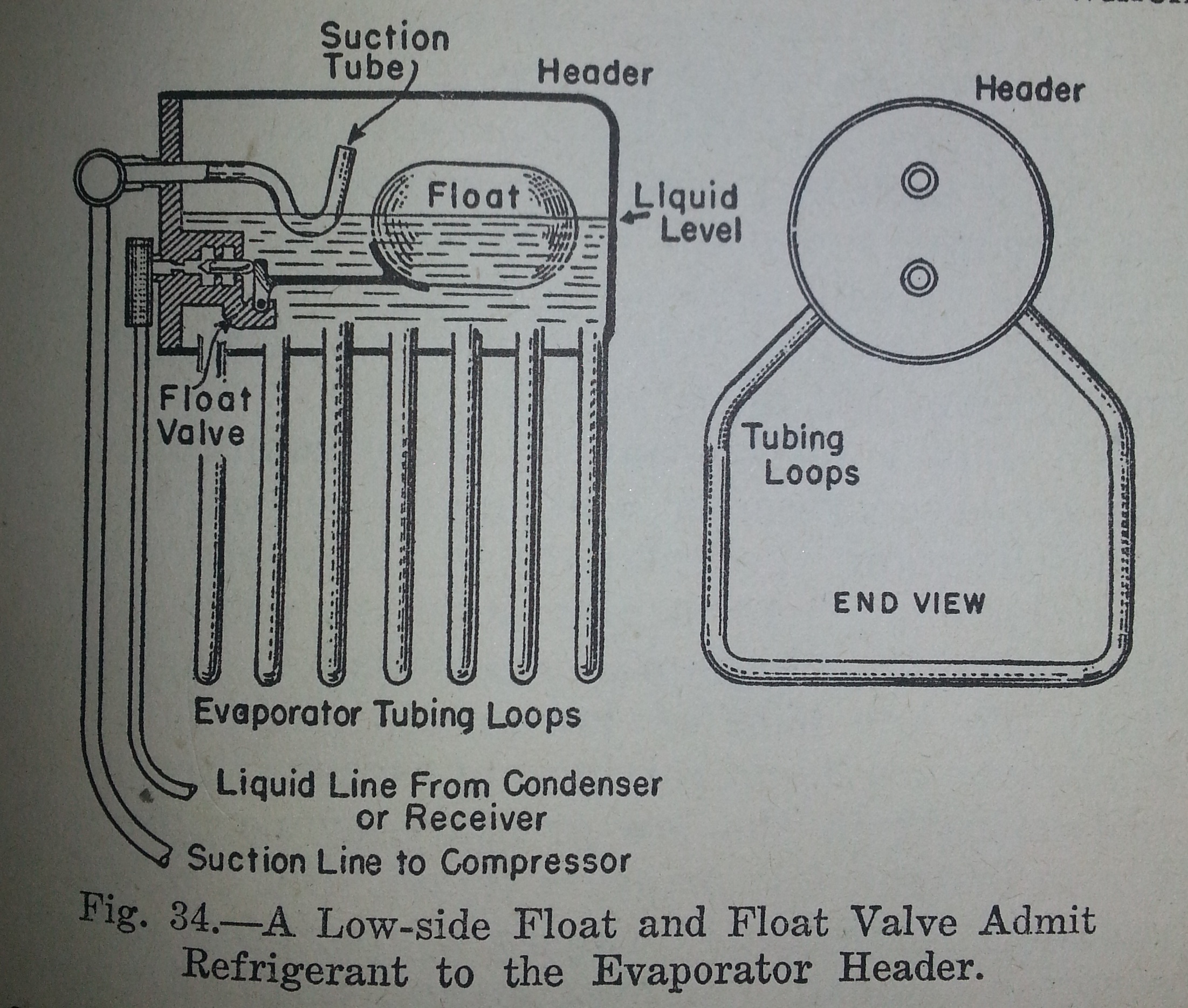
This is a gravity flooded evaporator depiction from a refrigerator in the 1920s or 1930s. They came in a number of different configurations, but this is a fairly good representation of the general idea. Instead of a single tube or series of parallel tubes with a common feed of high pressure refrigerant, this type of evaporator has a large volume or “header” where liquid refrigerant is admitted and saturated vapor withdrawn. The amount of low pressure liquid is maintained to fill approximately the bottom half of the header. The suction tube draws vapor from near the top of the header so as to avoid sucking liquid back to the compressor. In this flooded evaporator, as in most, a mechanical float valve controls the high pressure refrigerant inlet and when working properly will slowly “trickle” in just enough refrigerant to maintain the amount carried away by the suction tube. As the compressor runs, the suction pressure drops below the vapor pressure of the liquid within the header and this liquid begins to boil or “ebullates”. As it boils, it absorbs heat from header wall and from the tubing loops that communicate with the header. The wet refrigerant has very good thermal contact with the metal, more so than a wet vapor in a dry type evaporator. The vapor bubbles formed in the pool of refrigerant bubble to the surface in a process called ebulliton. The pressure at which all of this occurs is based on many factors including the capacity of the compressor, the surface area of the evaporator, the quality of high pressure refrigerant admitted through the float valve, the thermal conduction of the materials involved and so on.
A well designed vapor compression system utilizing a gravity flooded evaporator would generally favor a large evaporator capable of readily boiling off refrigerant vapor at a suction pressure only slightly below the vapor pressure given the ambient conditions. In other words, the compressor rating would be matched to the evaporator in such a way that the system would provide the needed refrigerating effect while the compressor “just keeps up”. If the compressor were any smaller (or slower), it would not provide the refrigerating effect and run continuously. Oversize the compressor and the suction pressure drops excessively, providing the refrigerating effect, but at a lower overall performance and compressor cycling. These gravity flooded evaporators lend themselves quite well to the use of variable speed compressors. When there is a larger load or more capacity is needed, the compressor speeds up, lowering the suction pressure and causing more violent ebullition in the evaporator and a larger delta T. When certain set points are reached or are neared, the compressor slows down, leading to higher suction pressure and increased COP.
Just like a dry evaporator, a gravity flooded evaporator requires some restriction between the high and low side otherwise no refrigerating effect occurs. Most advanced vapor compression systems measure the quality of the suction vapor and in a roundabout way the rate of refrigerant vaporization to determine if the refrigerant control should be opened slightly or closed. In a gravity flooded evaporator, usually a mechanical float maintains the liquid level in the header. With a float valve that does not cycle much, refrigerant can be admitted at the rate it is vaporized, determined by the fall in liquid level. Because of these differences, the suction vapor is in a dry saturated state with very little superheat at all times, unlike the dry evaporator which is usually designed to produce superheat.
As for pressure drop across the evaporator, I wouldn’t expect much. Considering the fact the refrigerant inlet and the suction tube are both in the header, I wouldn’t expect as much restriction as may be found in the long run of a dry evaporator. However, there can be another source of pressure drop in these devices. At or near the surface of the refrigerant pool, the liquid would most likely boil more readily than say, the refrigerant towards the bottom of a tubing loop because of the weight of liquid above adding to the pressure it is exposed to. I’m not sure how significant a characteristic this is, but definitely worth noting.
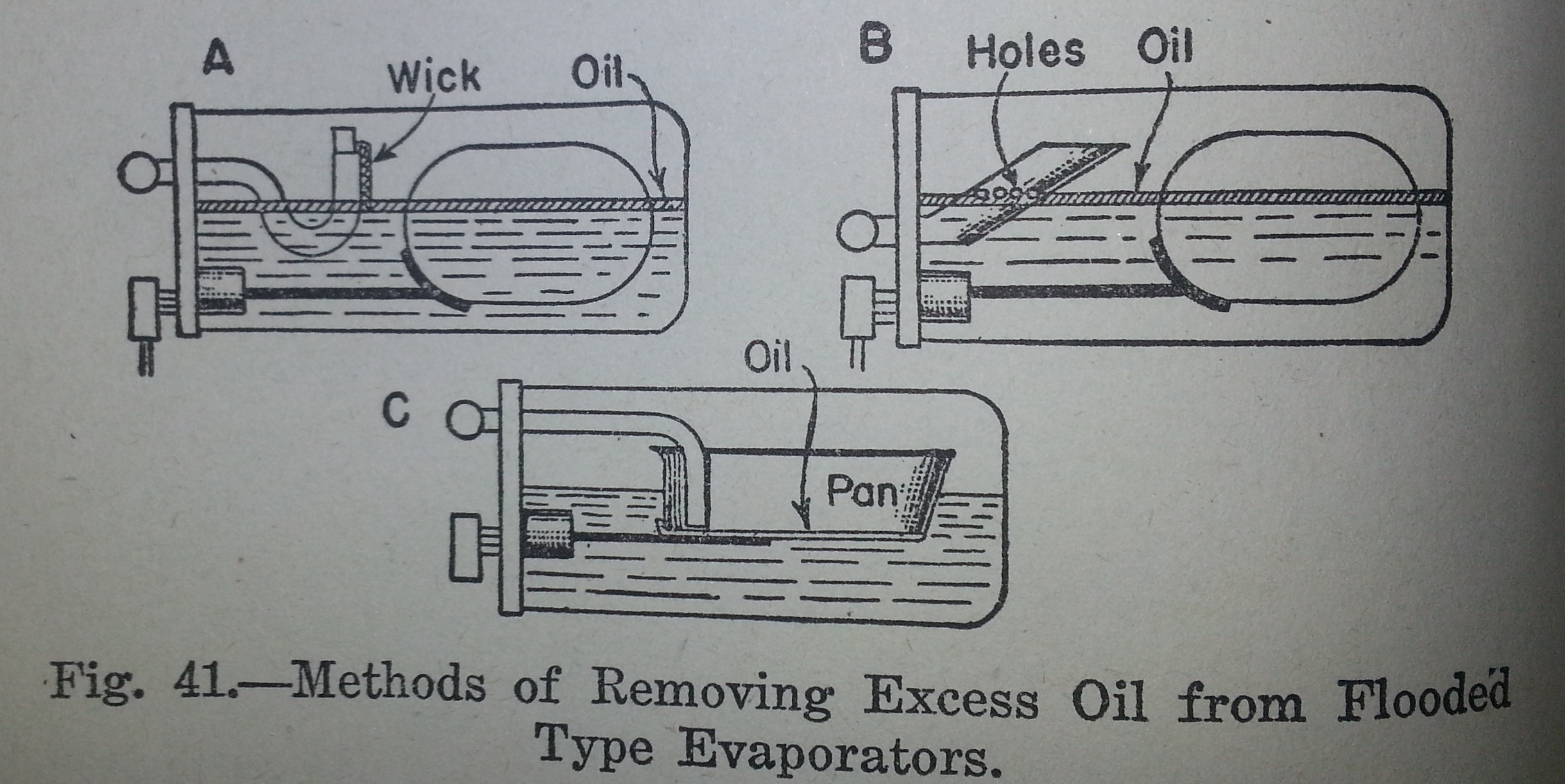
Some of the different ways oil was returned to the compressor. A concern when refrigerant is allowed to settle in part of a system. I’ll leave it to the reader to ponder over this. Personally, I favor the wick method. More detailed discussion of oil return in “1930s Household Refrigerators“.
Some Design Issues
Gravity flooded evaporators aren’t too common anymore, as far as I know other than large industrial chillers. Gravity flooded evaporators were common in refrigerators for a time, but then fell out of favor for a host of reasons. I would like to do some work with this type of evaporator and I have a series of projects designed around it. One problem with this is that the components to build one of these aren’t very common like dry evaporators are. Variations on the header and all of the tube loops are quite possible with copper tubing, fittings and pipe, but the float valve is a different matter. I’ve done some research to see if I could find a float valve out there that could be modified for my purposes and I’ve largely come up short. I’ve seriously considered making my own float valve by using some sort of float ball or tube to depress or actuate a valve pin and seat or ball and seat. A modified ball check valve seemed promising, but considering the pressure difference across it holding such a valve shut and the buoyancy of a practically sized float would require a good deal of mechanical advantage to open the valve. I think all of this is within the realm of possibility, but complicated and difficult. I don’t have a problem with difficult; if I did, I wouldn’t be be trying to redesign vapor compression systems. What I do have a problem with is over complication. Even if I could make a float valve that works, service and repair of it (not to mention the development) might require regular evacuation of all the refrigerant in the evaporator. That’s no good.
Another possibility not available to designers 80 years ago is an electronic float valve controlling an electronic expansion valve. I’m not even going there.
I would be great to keep the liquid sensing device outside the sealed system so that unless there is a leak or modifications are to be made, the evaporator need not be evacuated. The first comparison that comes to mind is the act of pouring warm water down the side of a tank of BBQ propane or other refrigerant and observing the frost line to determine the liquid level. One way I imagine doing something like this is with a TXV sensing bulb. As much as I’d like to get away from TXVs, their reliability, variety of size and application, and commonality, can’t be easily ignored. I’m considering a design where in the header of a gravity flooded evaporator, a “thermal well” is brazed in place where temperature readings can be taken of the inside of the header. A similar idea is used in hydronic heating boilers where thermostat bulbs or thermometers can get a good reading of water temperature without opening the system. What I imagine is a well just wide enough to fit the sensing bulb of the chosen TXV, that extends from the top of the header down towards the intended surface level for the refrigerant pool. The sensing bulb is placed within, perhaps with some heat conducting paste. When the machine is in operation, the TXV remains closed so long as the liquid level in the header is high enough to keep the sensing bulb cold. As the refrigerant level drops, the sensing bulb warms and the TXV admits more refrigerant into the header. Some questions arise because this is not the application for which these TXVs were designed for. They are designed to measure superheat so, I guess it is important that there be a detectable difference between the temperature of the liquid pool and the vapor produced. It probably makes good sense to draw the suction vapor across the sensing bulb well as it travels to the suction tube. This well might be vertical as just described or horizontal. The system may very well cycle open and closed or “hunt”. A wider pool of refrigerant in the header would change height less rapidly than a pool with little surface area. This may well help mitigate some possible hunting. Whatever it might do, I’m sure it will be interesting.
Long before I ever experiment with such a thing, I intend to make a purely manual version. That is, a gravity flooded evaporator with a manually operated refrigerant control, most likely a brass needle valve. There are many fundamental characteristics of a flooded evaporator that need to be explored before such an ambitious project of automatic control can be undertaken such as studying ebullition pressure versus suction pressure, bubble control, foaming, oil return, liquid convection in the refrigerant pool and ebullition initiators. It would be quite exciting to see the activity inside the header. That is why the header I intend to build at this time will be a piece of 2 inch copper pipe about 30cm long with high pressure sight plugs fixed to either end. The header would of course be mounted horizontally with the inlet refrigerant from the needle valve admitted from the top of the header and the suction tube drawing from the top of the header as well. Later versions might discharge the inlet somewhere under the surface to encourage flow in the pool. Liquid refrigerant would be admitted into the header until it’s level reaches approximately halfway up the sight glass. Once the machine is in operation, the needle valve will be opened and regulated so to maintain the liquid level. Simple as that. The compressor used, even a very small one, will most likely produce a very low suction pressure corresponding to a low evaporator temperature leading to rapid frost formation, insulation, lower heat flux, and even lower suction pressure. Depending on what I learn from this first model, I will of course add surface area in the form of tubes, fins, water jacket and so forth.
There are a great deal more plans and ideas, but I’ll save those for other posts.
M.C. Pletcher

[…] Helpful Resources The Great Gravity Flooded Evaporator | musings on entropy […]
Dear, I know it’s an old post, but take any oil separator, like this one: https://refrigeracionescobar.com.ar/wp-content/uploads/2018/06/IMG_3134-3.jpg you can open it, it has a floating system already made, pretty reliable. I am planning on designing a full system with flooded evaporator to reach low temperatures. Would you like to receive updates of my projects? Cheers
I sure would! 100yearfridge@gmail.com
I’m largely done with the concept of a flooded evaporator, and vapor compression generally. I will do another VC backup system for an ice refrigerator I’m building, but it will be a cap tube.