In Part 1 I complained a good bit about the design of conventional refrigerators. Since I was a little kid, I thought that surely their must be a better way make a refrigerator more convenient and at the same time consume less electricity. I’ve established that I would like to do away with the swinging door if possible using sliding doors wherever I can. A quick access door would be good too that allows a person to retrieve some common items without dumping all the cold air in the refrigerated cabinet each time the door is opened. My preferred embodiment of this would have either a flip up lid or sliding lid granting access to a rather shallow space the full length and width available. The space may or may not contain a turn table that would make better use of the depth of this volume. In most versions, this quick access area shares common air with several shelves above which are usually the width available and about half the from to back depth. The shelves are accessed from a vertical sliding window/door above the flip up lid. The question right now becomes: “What of the freezer?”.
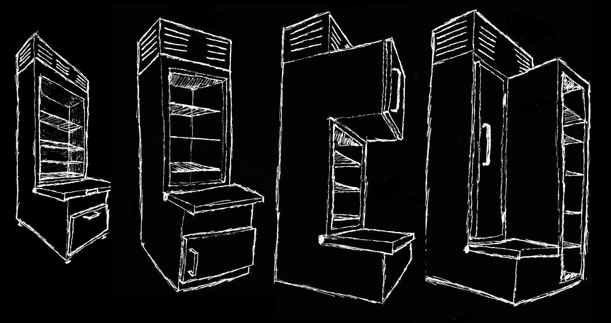
In the above four drawings, the two to the left are basically the same with the freezer at the bottom, accessed by a hinged door. The only discernible difference is one swings like a conventional freezer door and the other like an oven. I figure considering how low it is, the oven style is probably better. The third drawing is very strange. The only difference between it and the unit to the left is that now the freezer is on top the refrigerated space much like a conventional refrigerator. In my opinion, this design is less practical than the “hutch” because it forces the user to bend over for most items and it also limits the view. The reason I drew this and the odd looking vertical embodiment next to it which I won’t discuss much, is because of the difficulty in making these designs functional.
That is, if I want to build a refrigerator/freezer that requires very little energy to maintain the internal temperature, then it’s imperative that it not have to fight nature’s tendency to eliminate potentials, and instead be designed to take advantage of the fact that colder fluids tend to sink relative to warmer ones. So to effectively chill the refrigerated cabinet, it is best to cool the warmest air, which is usually at the top, so that it can sink displacing other warm air which rises to be cooled as well. This of course is convection, and if designed well, could eliminate most of the need for a circulating fan. The driving mechanism of this is the temperature difference between the warm air in the cabinet and the cooling surface. To be most effective, the cooling medium (tubes, fins, plate, etc.) should be high in the cabinet and somewhat separate from it in an air channel where cold, dense air can fall to the bottom; only to rise through the cabinet cooling the contents and then drawn back through the channel. This can be done with any of these configurations utilizing multiple evaporators for the different temperature compartments, but I would prefer to using a single evaporator, operating at a pressure corresponding to the temperature need to freeze a phase change material (PCM) that regulates cabinet temperatures consistently and can be relied upon to “holdover” the cold temperatures for an extended period of time.
 As I explained in Part 1, the freezer has been commonly found above the refrigerated space because cold air naturally sinks relative to warmer, so to keep a design simple my first inclination is to keep the freezer on top. If several kilograms of a depressed freezing solution of mostly water were confined in plastic bottles, and these bottles were chilled by a circulating liquid brine; the freezer space could be surrounded by a jacket of this brine/PCM or be built adjacent to a tank of it such that the temperatures desired in the freezer (-10C ?) would be maintained by constantly or periodically re-freezing the PCMs. The evaporator of the vapor compression system would be designed to cool this brine and if cooling were done from the top of the brine tank and if the appropriate baffles were put in place, then the brine could be made to circulate naturally.
So it should be plain to see why a freezer on top design, although not as practical to operate, at first appears the only viable solution if natural cooling methods are to be called upon. It’s not just cooling the refrigerated space that’s at issue here. Also, putting the brine tank/PCM at the top places the evaporator there and thus the whole compressor unit. If the tank were at the bottom for a bottom freezer design, then either the compressor unit would be low in the design which can be bad for air circulation or, if the compressor unit were placed on top would require an excessively long suction tube which brings with it pressure drop and superheat; both limiting factors in system performance.
It’s not just conventional wisdom here that is hard to overturn, it’s the layout of people’s kitchens. Re-designing a refrigerator to utilize the features I’m outlining is made more difficult because of the “hole” for the refrigerator in many homes is somewhat standardized in that it usually has a certain width and height limited by cabinets and other appliances. I like the idea of a complete overhaul, but then some people could not adopt it. So, I’m mostly limited to proportions that make the overall shape about as wide as it is deep and the height of an average man, or somewhere abouts and accessed mainly from the front rather than from two or more sides. Limitations can make design more fun.
In all the complicated iterations of designs I have gone through (many more than drawn), I’ve wracked my brain to make some pretty funky looking machines trying to fill all of my exhaustive requirements. I’d prefer to keep the clean and useful “hutch” style with the freezer on the bottom which requires finding a way to leave the evaporator on the top and find a way to cool the refrigerator too. Since I’m already planning to use a liquid brine to freeze the PCMs and encourage a natural circulation of it, why not build the majority of the tank in the bottom of the unit with the freezer space and extend columns of the brine up the back of the machine that would be cooled by the evaporator? (See note below) If designed well, the brine might be made to circulate by convection from the evaporator down to the PCMs and then back up again. This design might allow for the compressor/condenser/evaporator setup to have very short tubing runs. Also, the cold brine could somehow chill the warm air in the top of the refrigerated cabinet. My first impulse would be to bury all of these brine fluid lines and tanks deep in insulation, but there may be another feature here to be exploited.
 The above drawings are pretty crude but then, so is the idea. In both views the majority of the PCM “bottles” are in the bottom. They might be in some sort of plastic or metal tank that is somehow coupled to the freezer space to keep the contents frozen. Some manner of columns or pipes (Although I”m opposed to Vinyl, PVC might be a good choice for experimentation), would extend up to the cooling tank where the evaporator is near the top of the unit. These pipes would be arranged such that the coldest brine would be left to sink to the bottom of the PCM tank and the slightly warmer would rise to a level just above the cooling evaporator coils. As I said, this should all be very well insulated.
I described before a sort of “false back” inside the refrigerated space that would channel colder, denser air down, depositing it in the bottom and drawing warmer air from the top. Some means to chill that space would have to be found that could conduct that heat to the brine in the pipes within the insulation in the back wall. This could be metal fins or heat pipes maybe. Heat pipes add expense and complication so are to be avoided. If it’s not simple, I’m missing something. I realized, after I drew the above picture yesterday, that the brine to do the cooling should not be the coldest that has just been cooled and is sinking back to the PCM tank. No, if that sinking brine is heated by the cabinet then it’s density will decrease and the rate of flow will be affected. Instead, if the rising, “warmer” brine (that is still QUITE COLD), were used to cool the refrigerated space, the decrease in brine density due to the heat absorption would only accelerate it’s rise through the tube and increase the circulation rate of brine overall. In fact, I think it would be best to run the pipes carrying the rising brine through air channel in the refrigerated space itself with as much surface area added as is practical. A sort of natural system starts to take shape when one notices the countercurrent flow of the rising warming brine and the sinking cooling air. Countercurrent flows are generally superior to parallel flows when heat exchange is desired. Of course, some means to control the refrigerated cabinet temperature would be needed and I figure for this an air damper would be sensible that could control the flow of air through the channel. Maybe an automatic damper could be fashioned using an expanding thermostatic actuator.
Although I’ve been thinking about refrigerators on and off for a few years now, the previously described designs are very much in their infancy and their are a lot of complicated problems that require simple answers. Why go to these lengths to redesign something as common and well established as a refrigerator? It’s fun, that’s why. This isn’t just a series of thought experiments; I intend to build one of these or something like it. This is part of the Killcap Refrigerator project which, beyond just making it practical and efficient, also seeks to make it serviceable, recyclable, modular and built from non-toxic materials. The integration of the PCMs is to give it good thermal storage properties allowing for lapses in power like that of utility blackouts, intermediate supply from renewables and possibly periodic human mechanical input.
As I dive back into hands on refrigeration practices I’ll be building various testing platforms to evaluate different ideas. Eventually, In intend to standardize my analytical techniques and measurement equipment so that I can model vapor compression systems and evaluate various components and system parameters. One of my first projects is going to be a water/brine chiller that pumps the heat to the atmosphere with a fan and radiator. I’m probably going to salvage the parts from some dehumidifiers I have laying around and develop my brazing techniques by fashioning things like evaporator headers and custom made receivers. This first test platform will be pretty crude but will hopefully have a lot to teach.
Note: The above design, still very much in it’s infancy has one major flaw I just realized a day later. The PCMs behind the freezer space could do fine in maintaining the freezer temperature and the brine flow may flow fine while the compressor runs, but during the off cycle the majority of the cold storage is in the bottom of the circulating brine system which is not going to allow for proper convective flow. Little if any I’m sure which kind of defeats the purpose. Instead, the majority of the PCMs should be in the top of the brine system so that convection continues when the compressor is off. In effect, this would be quite similar to the construction of a “freezer on top” model, but instead of a brine loop dropping for refrigerated cabinet cooling only, it would surround the freezer compartment or at least a stainless steel plate heat exchanger in the top of the freezer compartment.
M.C. Pletcher

Questions or Comments?