The refrigeration compressor is where all the ‘magic’ happens. To understand the process of compression is to understand the fundamental principles of mechanical refrigeration. A compressor is the mechanism that allows us to reuse that same refrigerant over and over. It is the component in a system which more than any other determines how close to the ideal thermodynamic limits one can obtain, but at the same time is itself unequivocally linked to the conditions throughout the system. Many refrigeration books start off explaining heat and temperature, then phase change and finally a simple refrigeration example where by a tank of liquid with a low boiling point in atmospheric pressure is allowed to slowly release though a coil to refrigerate a space. The liquid, (often anhydrous ammonia) vaporizes quickly as it comes in contact with the warm coil wall inside the refrigerated space. Once the ammonia fully vaporizes it is released to the atmosphere. This description is usually accompanied with an explanation of how expensive this model is since the ammonia must be replenished. Of course it is expensive, and that is why we apply pressure.

In order to get the refrigerant gas into it’s original liquid condition, we must remove the heat it gained from the refrigerated space via the ‘evaporator’. Of course, we have no space cold enough to absorb the heat at that temperature and re-condense the gas into liquid. If we did, we would not need to refrigerate a space in the first place. So, in order to emit the heat stored in the vapor, we must raise it’s temperature higher than the surrounding environment (often, the ambient air). It is desirable to do this without adding any extra energy to it. It will be seen that such a condition is not possible. I am talking about compression. There are several types of compressors, but I am most interested in the reciprocating type most familiar to the reader as an air compressor or the construction of an internal combustion engine.

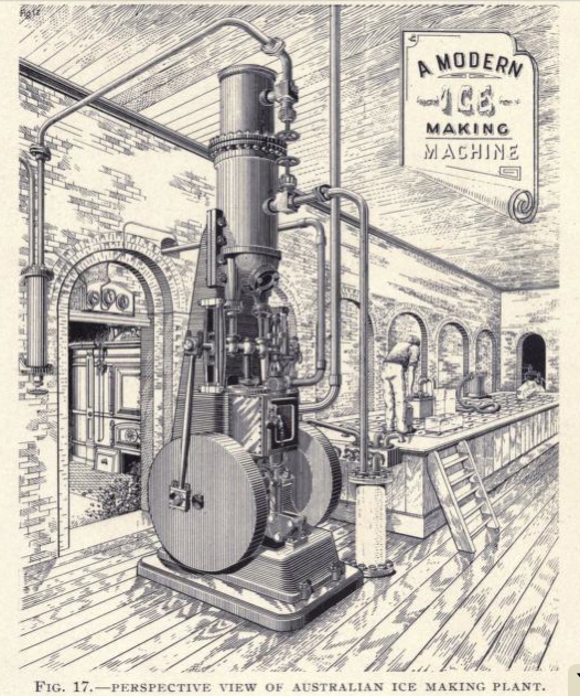
Above is an illustration from a book, ‘Refrigerating Machinery’ by Ritchie Leask 1895. It is certainly a very dated illustration, but it does well in representing the basic components in a mechanical vapor compression system. In the center is the compressor P with discharge and suction valves below. The discharged high pressure gas passes to the left through line W where it is cooled to the point of condensation by water circulated in the tub. From there it is a high pressure liquid; the pressure dictated by the temperature difference needed between the hot discharge gas and the cooling water to get sufficient heat transfer to the water resulting in liquefaction or more commonly known as condensation. Thus the term ‘condenser’. The liquid is cooled as much as possible before passing through a pressure control valve, D. This valve, along with the compressor, divides the system into the high side and the low side. After the valve, a portion of the now low pressure liquid will violently boil into a vapor and in doing so will cool the remainder of the liquid to a temperature making it capable of absorbing heat from it’s environment. In this case it may be a low temperature salt brine or just perhaps water for the manufacture of ice represented by A. This low pressure liquid in the evaporator will absorb heat from the the liquid A and itself boil away into a vapor state carrying that heat away with it through the suction line back to the compressor. The pressure in which the suction line and thus the evaporator is kept will be determined by the the properties of the refrigerant used and the temperature desired resulting in the desired refrigerating effect.
The pressures in this system if it used Propane as the refrigerant may be 30 psi on the low side and 160 psi on the high side. These pressures are associated with about 8 degrees F and about 95 degrees F. Different refrigerants are associated with different pressure/temperature relationships. 30 psi and 160 psi can vary in this case greatly depending on the conditions the machine operates. The compressor will discharge vapor at a sufficient pressure such that the temperature of condensation (the same as the boiling point), is high enough that heat leaves the hot vapor and is absorbed by the cooling water, there by resulting in condensed high pressure liquid. Any pressure higher than this is unnecessary and results in extra work for the compressor. Likewise, through drawing in suction line vapors and discharging them to the high side, the compressor ‘rarifies’ the molecules in the evaporator and lowers the pressure on the liquid causing it to boil at a low temperature and absorb heat from the environment, making water ice perhaps. The suction pressure necessary corresponds with a temperature that will perform the refrigerating effect. Any lower temperature requires a lower pressure and puts extra work on the compressor. These two pressures, the low side and the high side dictate the ‘compression ratio’; the larger the difference between the two absolute pressures, the more work done by the compressor. It is important to keep the compression ratio low as will be seen later.
 The above cross section shows a horizontal single acting reciprocating compressor with ‘poppet type’ valve construction. The artist added what is known as an ‘indicator card’ to the compressor volume which is a graph depicting the pressure and volume relationship in the compressor throughout a typical stroke. Notice the compressor piston will extend in from the right, decreasing the cylinder volume there by compressing the vapor inside. When that pressure exceeds the pressure on the ‘high side’; often within the condenser, the gas will be forced through the lower valve depicted on the left side of the drawing. The valves are not mechanically controlled as they are in an internal combustion engine for the reason that changes in timing are dependent on several factors which can fluctuate often. Instead, a small spring holds the valve closed until the pressure difference inside the cylinder is greater than the high side and it is forced open. Once the piston comes to ‘top dead center’ or the closest point to the valves, it will begin to return to the bottom at which point the small remaining vapor in the cylinder will begin to expand which is accompanied by a pressure drop. The pressure on the high side outside the compressor is now higher than the cylinder pressure and so the discharge valve is forced shut. The cylinder continues to expand. If the piston had forced all of the gas in the cylinder out, there would have been no space in the cylinder left which means the piston would have to contact the cylinder head. Of course in reality this doesn’t happen and a small amount of gas remains in the cylinder in what is called the ‘clearance space’. There is a term used to describe the amount of volume capacity in the whole cylinder compared to the volume displaced is the ‘apparent volumetric efficiency’. It will be seen that it varies from the true volumetric efficiency. If all the gas had been discharged on the compression stroke, then upon the suction stroke a perfect vacuum would be formed immediately. The pressure behind the suction valve or intake would be higher and the valve would be forced open instantly, filling the cylinder volume to 100% capacity. In reality, the small remaining gas in the clearance space must re-expand to a pressure lower than that of the suction line before the valve is forced open. Once it does, the valve opens and fills the cylinder with vapor at or near the suction pressure. At the bottom of the stroke the valve should close and compression starts again. This process repeats several hundred times a minute in large compressors and several thousand, in smaller.

Above is an indicator card from an ammonia compressor and is taken from ‘Refrigeration – Including Household Automatic Refrigerating Machines’ by James A Moyer and Raymond U Fittz 1928. Often, in refrigeration texts one might see theoretical pressure/temperature diagrams, but the above diagram was probably taken from a real compressor using a mechanical measuring device which draws on a piece of paper with a lead pencil. There is a lot of interesting characteristics describable from the above. As I said before, the indicator diagram represents the relationship between volume and pressure in the action of a moving piston inside a cylinder. The distance A represents the total travel of the piston from from the bottom of the suction stroke at left and the top of the compression stroke on the right. Pressure is of course represented by the vertical height of the lines. From the solid line EG represents where G is the point where the discharge valve opens. GJ is the discharge of compressed gas into the high side. Line JM is the portion of the suction stroke where the remaining gas in the clearance volume re-expands with the point K being the suction valve opening and the dip being the extra pressure to overcome the spring of the valve. Distance D is the portion of the stroke where no additional gas is drawn into the cylinder. The line ME is the portion of the suction stroke where fresh vapor is drawn into the cylinder at slightly below suction pressure. It can be seen that the suction stroke must maintain a slightly lower pressure in order to facilitate valve opening and to create a potential difference for vapor movement. Similar can be said for the discharge, but instead a higher pressure is needed. It can be seen that the distance B represents the travel distance of the compression stroke where the pressure of the suction vapor is lifted to the pressure of the actual suction line before any additional pressure is added above this. So, the loss in stroke D due to clearance space and B due to suction valve forces leaves a working travel of C. The ratio of C/A represents the apparent volumetric efficiency. It becomes visually apparent that an increase in clearance volume would decrease apparent volumetric efficiency as seen by line JN. Also, restrictions such as a stiff suction valve spring or small valve opening can increase the length of distance B.
.

Another indicator card with two areas shaded representing extra work done by the compressor.
.

This is a mirror image of the other indicator cards, but is showing the same type of information. In an ideal situation, the suction vapor drawn into the cylinder would be in a dry saturated condition. That is, it will be in a fully gaseous state at the very same temperature it boiled at in the evaporator without any additional heat added that would raise it’s temperature. When compression of a gas occurs, work is done on it in reducing the volume and bringing all of the molecules closer together. The mechanical work done corresponds to heat added to it. If upon compression of this dry saturated vapor, the heat of compression were absorbed by the cylinder walls, the temperature of the gas would remain constant. If instead, no heat were removed or added to the compressing gas it would said to be adiabatic compression. This is closer to what actually occurs in a reciprocating compressor. From the indicator card above you can see the compression curve follows the adiabatic line closely. The gas is probably absorbing some heat from the hot compressor because of superheat. Superheat is the state of a gas when the temperature of it is higher than that of the same gas at dry saturation; generally the case at the discharge of a refrigeration compressor. Usually the high pressure discharge gases must be cooled in the condenser to the condensation temperature before the heat of the original refrigerating effect can be removed. The extra heat is that of compression and can result in discharge temperatures a great deal hotter than the condenser. The problem with adiabatic compression is that as the heat of compression drives the temperature of the gas higher and results in a more rarified, expanded gas which requires yet more work (and heat of compression), to raise the pressure. So it is good practice to cool the compressor head adequately to prevent excessive superheating, but not so much that liquid condenses in the cylinder. Even small amounts of liquid in the cylinder can cause damage including broken valves, piston rods, cracks, etcetera, but can also re-expand if trapped in the clearance space and have detrimental effects on volumetric efficiency.
Superheat has an effect on the suction vapor as well. Ideally, dry saturated vapor is pulled into the cylinder, but usually a slightly superheating suction vapor occurs in it;s traveling from the evaporator to the suction valve and of course some suction heating occurs when the vapor enters the warm cylinder, raising the temperature. Superheated suction vapor has multiple drawbacks. Not only does it add to the superheat of compression and require more work, but it lowers the specific volume of the gas. A higher temperature gas is less dense than a lower one, so less mass of refrigerant is drawn into the cylinder for compression. In this case and in most, mass flow in the refrigeration circuit is more important than volume displacement. Liquid and vapor mass absorb heat and provide the refrigerating effect so it is important to move as much of it per compressor stroke.
Theoretically, a superheated gas in the clearance space, upon re-expanding will return most of the work of compression to the piston. This may have been somewhat true when large bore reciprocating ice making machines chugged along at 60 rpm driven by huge steam powered flywheels. That work may have been returned to the energy storage system, but in today’s small, fast reciprocating compressors lacking any energy storage I think it’s more likely to add to the superheat of the incoming suction vapor there by reducing volumetric efficiency and increase compressor load.
Higher compression ratios only exacerbate all of these problems, decreasing volumetric efficiency, raising the head pressure, lowering the mass flow rate; some of which can be made up for by increasing compressor speed. Although an increase of speed will often increase the refrigerating capacity, it also adds heat from mechanical friction as well as throttling friction in the valve ports, can advance a problem sometimes known as ‘wire drawing’ where the head pressure is higher and the suction pressure lower to allow for vapor travel through insufficiently sized valve ports, and problems associated with fluid inertia with a rapidly reciprocating piston.
Sometimes, when low temperatures are required, the associated compression ratio necessary would be uneconomical for a single compressor to accomplish without severe losses in performance, a second stage is employed where a low pressure compressor may compress the suction vapor part way to the final condensation pressure needed and then, a second compressor picks up from the first and finishes the work. Between these two stage an ‘intercooler’ drives off some of the superheat from the first stage there by reducing the work necessary in the second stage. There are several advantages to a design like this and can include many more stages if needed.
I grow tired of writing about compressors for now, but there will be more in the future with some ideas on small scale reciprocating compressor improvements I intend to test.
M.C. Pletcher

Questions or Comments?